Magnetic Pressure Valves
mechanical and fluid systems
Magnetic Pressure Valves (KSC-TOPS-50)
A magnetically retained pressure relief valve
Overview
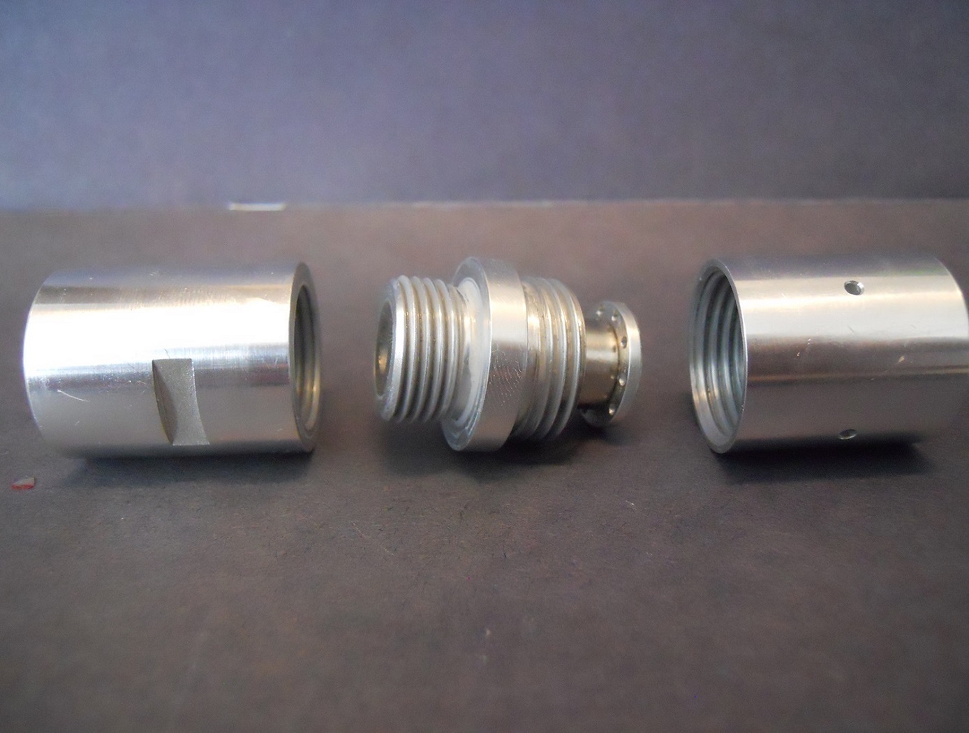
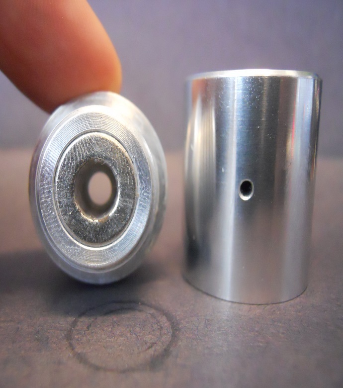
NASA Kennedy Space Center seeks partners interested in the commercial application of a magnetically retained fast-response pressure relief valve that is designed to fully open at precise cracking pressures and that operates in a fully open/fully closed manner. The use of a magnetically controlled relief valve as opposed to a spring-based relief valve enables quick-open on/off relief operation when overpressure is reached. This is due to the rapid decay of the magnetic field as the fluid medium pushes the valve poppet to an open position. Spring-based relief valves require increasing pressure and force to continually compress the spring and open the relief valve. This requirement greatly complicates the design of a system relief mechanism. A magnetic relief valve reduces these design complexities by eliminating the spring.
The relief valve mechanism is fully sealed and is isolated from the flow path of the fluid/gas media. This may lead to lower maintenance than is currently required for pressure relief valves. Existing relief valve springs are exposed to corrosive environmental factors and system fluids. This environmental exposure leads to corrosion that can cause changes in the cracking pressure.
The Technology
The innovation was developed for low-pressure pneumatic testing of a vacuum chamber in the Kennedy Cryogenics Test Laboratory. Standard relief valves that utilize mechanical springs did not function adequately at the low pressure (16 pounds per square inch [psi]) required by the inventors during testing.
The technology is an improvement over current pressure relief valves using spring mechanisms. Typical pressure relief valves are normally held closed by a spring. After a relief valves cracking pressure is reached, the spring is compressed and the valve opens to relieve excess pressure. The NASA valve eliminates the need for a spring by instead incorporating magnets to hold the poppet relief valve in the closed position. The use of magnets in a pressure relief valve exploits the exponential decay of the magnetic field between two magnets as they are separated. This leads to a faster acting valve that does not require an increasing force to open the relief valve after cracking pressure has been surpassed, as is the case in standard pressure relief valves.


Benefits
- Fully on/fully off valve operation at design pressure
- Improved crack pressure accuracy at low operating pressure
- Reduced maintenance in corrosive environments
- Handles larger flow rates and larger range of pressure values
Applications
- Pressure Vessels
- Vacuum Chambers
- Low Pressure Systems
- Basic Industrial Systems
- Gas and Liquid Systems
Similar Results

Magnetically Damped Check Valve
NASA's Magnetically Damped Check Valve invention is a damping technology for eliminating chatter in passive valves. Because valve failure in space missions can cause catastrophic failure, NASA sought to create a more reliable check valve damper. The new damper includes the attachment of a magnet to the poppet in a check valve to provide stabilizing forces that optimize flow and pressure conditions. Test results have proven that the Magnetically Damped Check Valve offers substantial benefits.
The Magnetically Damped Check Valve works over a wide range of flow dynamics and eliminated chatter under all flow conditions tested, allowing valves to operate under various flow rates and pressures without a risk of degradation or total destruction from chatter. This technology could provide a more simple and cost-effective solution for valve manufacturers and system designers than solutions currently available in the market.
Applications for the new valve include use in aerospace or industrial processes. NASA's damping technology was originally designed for check valves, but could also benefit pressure regulators, relief valves, shuttle valves, bellows sealed valves or other passive valves.

Pilot Assisted Check Valve for Low Pressure Applications
Check valves are traditionally designed as a simple poppet/spring system where the spring is designed to equal the force created from the sealing area of the valve seat multiplied by the cracking pressure. Since the valve seat diameter in these types of valves are relatively small, less than 0.5 inches diameter, a low cracking pressure required for back pressure relief devices results in a low spring preload. When sealing in the reverse direction, the typical 20 psid storage pressure of the cryogenic fluid is not enough pressure force to provide adequate sealing stress. To better control the cracking pressure and sealing force, a bellows mechanism was added to a poppet check valve (see Figure 2). The bellows serves as a reference pressure gauge; once the targeted pressure differential is reached, the bellows compresses and snaps the valve open. Prior to reaching the desired crack pressure differential, the bellows diaphragm is fully expanded, providing sufficient seal forces to prevent valve flow (including reverse flow) and undesired internal leakage. Room temperature testing of cracking pressure, full flow pressure, and flow capacity all showed improvements. The overall results of the test proved to be 10-20 times greater than conventional check valves with no internal leakage at three different pressure differentials.

Variable-Aperture Reciprocating Reed (VARR) Valve
The VARR valve has been designed to provide a variable-size aperture that proportionately changes in relation to gas flow demand. When the pressure delta between two chambers is low, the effective aperture cross-sectional area is small, while at high delta pressure the effective aperture cross-sectional area is large. This variable aperture prevents overly restricted gas flow. As shown in the drawing below, gas flow through the VARR valve is not one way. Gas flow can traverse through the device in a back-and-forth reversing flow manner or be used in a single flow direction manner. The contour shapes and spacing can be set to create a linear delta pressure vs. flow rate or other pressure functions not enabled by current standard orifices. Also, the device can be tuned to operate as a flow meter over an extremely large flow range as compared to fixed-orifice meters. As a meter, the device is capable of matching or exceeding the turbine meter ratio of 150:1 without possessing the many mechanical failure modes associated with turbine bearings, blades, and friction, etc.

Low-Cost, Long-Lasting Valve Seal
NASA's technique simplifies the seat installation process by requiring less installation equipment, eliminating the need for unnecessary apparatus such as fasteners and retainers. Multiple seals can be installed simultaneously, saving both time and money.
NASA has tested the long-term performance of a solenoid actuated valve with a seat that was fitted using the new installation technique. The valve was fabricated and tested to determine high-cycle and internal leakage performance for an inductive pulsed plasma thruster (IPPT) application for in-space propulsion. The valve demonstrated the capability to throttle the gas flow rate while maintaining low leakage rates of less than
10-3 standard cubic centimeters per second (sccss) of helium (He) at the beginning of the valves lifetime. The IPPT solenoid actuated valve test successfully reached 1 million cycles with desirable leakage performance, which is beyond traditional solenoid valve applications requirements. Future design iterations can further enhance the valve's life span and performance.
The seat seal installation method is most applicable to small valve instruments that have a small orifice of 0.5 inches or less.

Cryogenic Hydraulically Actuated Isolation Valve
NASA's cryogenic isolation valve technology uses solenoid valves powered by direct current (DC) electrical energy to control and redirect the energy stored in the upstream line pressure. Powering the solenoid valves only requires a DC power source capable of supplying 22 watts that can be distributed and controlled in an on/off manner. By achieving actuation using only upstream line pressure and a 22-watt DC power source, many additional support systems that are required for electromechanical and pneumatic actuation are eliminated. This reduction of parts results in several benefits, including reduced footprint, weight, and potential cost of the valve in addition to lower energy consumption.
NASA fabricated several operational prototype valves using this technology for a rocket company. The table below shows the results of tests performed on these valves under cryogenic conditions. Please contact the NASA MSFC Technology Transfer Office for additional information.


