Optical concentration sensor for liquid solution
Sensors
Optical concentration sensor for liquid solution (KSC-TOPS-91)
Light scattering approach to precisely measuring solution concentrations
Overview
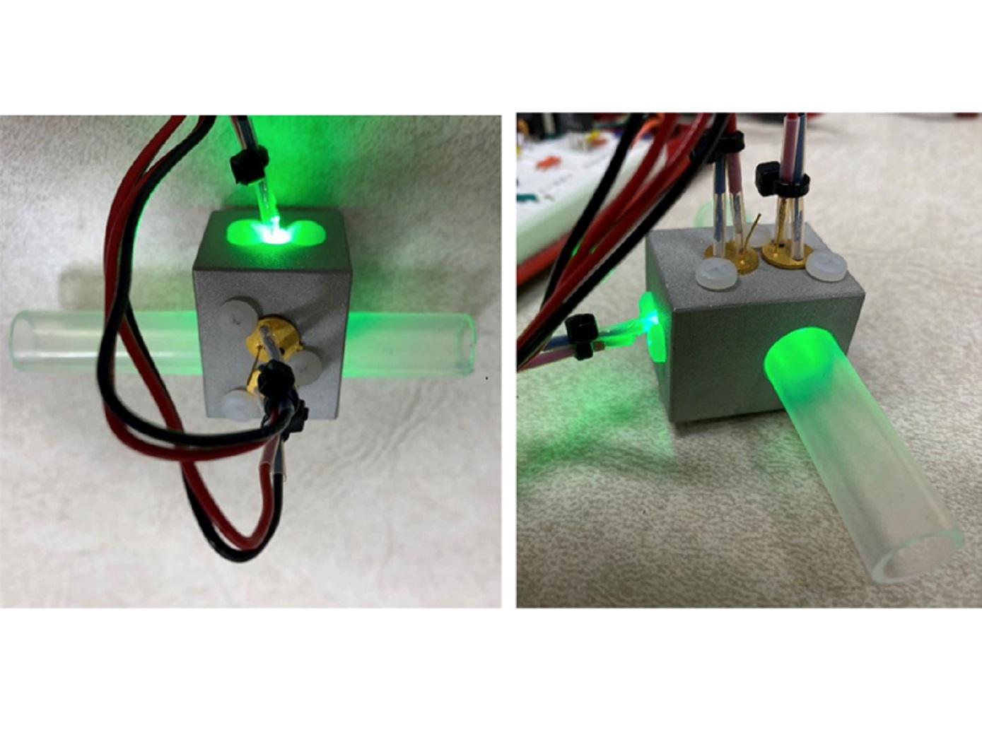
Innovators at the NASA Kennedy Space Center have developed a new optical sensor for measuring concentration in a liquid solution. The sensor was designed for measuring the pretreat solution concentration within the Universal Waste Management System (UWMS), a specialized toilet designed for the International Space Station (ISS) and other future missions. The sensor was developed to replace the current pretreat concentration sensor within the UWMS that uses electrical conductivity instead of light-based methods. Using established methodologies and commercial components, the new sensor can precisely measure the concentration or pretreat within the waste treatment solution using the light passed through and scattered by the solution. The optical sensor can be adapted to measure the concentration of solutions across various industries.
The Technology
Typical concentration sensors, like the one initially used in the UWMS, rely on changes in electrical conductivity to measure the concentration of a solution. These measurements using conductivity are prone to voltage drift over time, leading to unreliable measurements as the sensor ages.
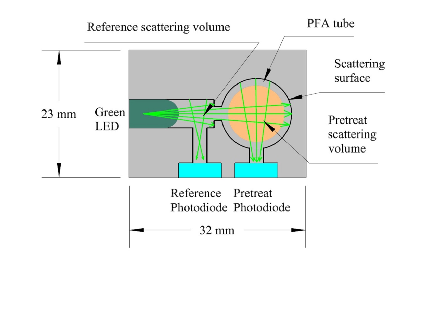
The optical sensor developed here uses light scattering to measure the solution concentration without the issue of voltage drift. In this sensor, light from a green LED is passed into the sensor housing where it hits a first detector (i.e., a photodiode) to establish a reference of the amount of light before scattering. Simultaneously, the light from the LED scatters through the pretreat solution and then hits a second photodiode to measure the amount of light after scattering. The difference between the amount of light measured by the two detectors is used to calculate the concentration of the pretreat solution (based upon Beer’s Law). The optical concentration sensor has been demonstrated to effectively measure pretreat concentrations in both still and flowing liquid conditions and is resistant to contamination issues as necessitated by the UWMS.
The optical pretreat concentration sensor is at technology readiness level (TRL) 4 (component and/or breadboard validation in laboratory environment) and is available for patent licensing.


Benefits
- Straightforward to adopt: the optical sensor is built with commercial components and is based on established techniques, making commercialization simpler
- Less prone to voltage drift and contamination: the light-based method of this technology should outperform conductivity-based sensors in these regards
- Improved reliability: the use of a scattering cell samples light passing throughout the solution, ensuring reliability of readings
- Relatively compact: the sensor should be able to be miniaturized to roughly one cubic inch
Applications
- Aerospace: measuring solution concentrations in fluid management systems (e.g., waste management, fuel management)
- Industrial: measuring solution concentration in food and beverage processing, pharmaceuticals production, medical devices, etc.
- Wastewater processing: measuring solution concentration in terrestrial wastewater treatment across various scales (e.g., municipal wastewater treatment plant, decentralized chemical toilet)
Technology Details
Sensors
KSC-TOPS-91
KSC-14500
|
Tags:
|
|
|
Related Links:
|
Similar Results

Enhanced Fabrication Improves Temperature Sensing in Cryogenic Humid Environments
This technology was developed to improve Armstrong's multi-patented FOSS system, which has long been used to measure temperature and liquid levels in cryogenic environments. When the sensing system's fibers trapped humidity from the surrounding environment before their submersion into cryogenic liquids, the moisture adversely affected outputs. A new manufacturing process solves this problem, increasing reliability and accuracy not only of NASA's FOSS but also any fiber optic sensing system.
How It Works
Armstrong has developed a two-step process to assemble the sensors. First, the bare sensor fiber is inserted into an oven to expel all moisture from the fiber coating. Then, the moisture-free fiber is placed inside a humidity-controlled glove box to prevent it from absorbing any new moisture. While inside the glove box, the fiber is inserted into a loose barrier tubing that isolates the fiber yet is still thin enough to provide adequate thermal transfer. The tubing can be further purged with various gases while it is inside the glove box to provide additional moisture isolation.
This innovation is particularly useful for fiber optic systems that measure temperature and that identify any temperature stratifications within cryogenic liquids.
Why It Is Better
This process seals sensor fibers from environmental moisture, enabling fiber optic sensing systems to operate reliably in humid environments. The innovation eliminates erroneous readings that can occur due to moisture collection on the fiber sensors.
For more information about the full portfolio of FOSS technologies, see DRC-TOPS-37 or visit https://technology-afrc.ndc.nasa.gov/featurestory/fiber-optic-sensing

Contaminated Water Treatment
This invention is a system and associated method that is a two step process. It provides a contaminant treatment pouch, referred to as a urine cell or contaminant cell that converts urine or another liquid containing contaminants into a fortified drink, engineered to meet human hydration, electrolyte and caloric requirements. It uses a variant of forward osmosis (FO) to draw water from a urine container into the concentrated fortified drink as part of a recycling stage. An activated carbon pretreatment removes most organic molecules. Salinity of the initial liquid mix (urine plus other) is synergistically used to enhance the precipitation of organic molecules so that activated carbon can remove most of the organics. A functional osmotic bag is then used to remove inorganic contaminants. If a contaminant is processed for which the saline content is different than optimal for precipitating organic molecules, the saline content of the liquid should be adjusted toward the optimal value for that contaminant.

Pre-Treatment Solution for Water Recovery
The pre-treatment solution increases the solubility of calcium in urine brines by reducing the concentration of sulfates. When the solution is properly dosed, it enables biological, physical, and chemical stabilization of flushed urine for storage and distillation up to a steady 87% water recovery, as realized aboard the U.S. segment of the ISS, without precipitation of minerals such as gypsum.
Turning wastewater or seawater into potable water requires three important steps shared by the UPA and Water Recovery System (WRS) aboard the ISS: 1) pre-treatment, 2) distillation or membrane filtration, and 3) transport and storage of potable water and brine. Added during the first step, the pre-treatment solution improves the efficiency of the UPA by reducing the formation of solid precipitates caused by urinary calcium, sulfate ions, and sulfuric acid. This reduction in-turn creates less acidic brines which means more water can be recovered along with less surface scaling and clogging, further increasing recovery. As an added benefit, the solution contains a biocide that prevents the growth of bacteria and fungus, thereby increasing storage time of the treated urine.
Although the pre-treatment solution was developed for the ISS’s UPA , the technology can potentially be used on Earth to pretreat contaminated water from organic-laden, high-salinity wastewaters. Adding the solution is a simple process that can be scaled to fit demand. It has the potential to improve water recovery in many applications such as: desalination plants, brackish water treatment, mining water treatment, hydraulic fracturing operations, and more. The pre-treatment solution may also lend itself for use in the transport and storage of wastewater due to the solution's ability to prevent microbial growth.

Streamlined Liquid Level Sensing Using Fiber Optics
Armstrong has developed a robust fiber optic–based sensing technology that offers extraordinary accuracy in liquid level measurements. The sensing system uses fiber optic Bragg sensors located along a single fiber optic cable. These sensors actively discern between the liquid and gas states along a continuous fiber and can accurately pinpoint the liquid level.
How It Works
The technology uses a resistive heater wire bundled with the optical fiber. The heater is pulsed to induce a local temperature change along the fiber, and the fiber Bragg grating data is used to monitor the subsequent cooling of the fiber. The length of fiber in the liquid cools more rapidly than the portion of the fiber in the gas above the liquid. The measurement system accurately establishes the location of this transition to within 1/4-inch.
Why It Is Better
Armstrong's liquid level sensing technology was originally developed to measure cryogenic liquid levels in rockets, and it represents a significant advancement in the state of the art in this application. Conventional methods for measuring cryogenic liquid levels rely on cryogenic diodes strategically placed along a rod or rack. The diodes are mounted in pre-selected, relatively widely spaced positions along the length of a rod; this configuration provides limited, imprecise data. Furthermore, each diode on the rod has two wires associated with it, which means a single system may require a large number of wires, making installation, connectivity, and instrumentation cumbersome.
Armstrong's novel technology provides liquid measurements with much greater precision, achieving measurements at 1/4-inch intervals. Furthermore, the streamlined system uses just two wires, which greatly simplifies installation and instrumentation. Due to its extraordinary accuracy and ease of use, Armstrong's measurement system offers important advantages for a wide range of applications beyond cryogenic liquids.
In Addition
Researchers have developed a new manufacturing process that improves the ability of fiber optic sensing systems to measure temperature and liquid levels when operating in humid environments. The process involves eliminating moisture from the optical fiber coating, then completing the sensor assembly within humidity-controlled conditions. The resulting sensor hardware provides precise and accurate measurements even when operating in a humid environment.
For more information about the full portfolio of FOSS technologies, see DRC-TOPS-37 or visit https://technology-afrc.ndc.nasa.gov/featurestory/fiber-optic-sensing

Multi-Parameter Aerosol Scattering Sensor
Originally developed to demonstrate a highly accurate, low-false-alarm, early fire detection system in space, this advanced technology level system utilizes a durable, low-cost, compact laser source and detector array, similar to CD/DVD player technology, to analyze the interaction of light with particles. The smart system is ideal for detecting a diverse range of particles found in pollution, emissions, fire and other atmospheric toxins while introducing a flexibility that enables its use in multiple environments, especially when coupled with UAVs or other remote platforms.
The MPASS contains a number of features that allow users to make the most of its pioneering capabilities. The self-contained system is lightweight and has been miniaturized and packaged to easily fit into the palm of your hand. A USB port enables the system to be powered, configured, and accessed through its onboard central processing unit. The advanced graphical user interface, custom software, and optimized algorithm allows the user to select known properties when applicable, and to program the system for maximum performance. The dashboard also provides visual feedback through graphical displays, making it easy to analyze the data and make real-time decisions. The system is designed with Bluetooth expansion capability, adding flexibility and communication through potential custom cellular phone applications. Once programmed, the battery-powered wireless sensor system opens the door to monitoring remote areas and extreme environments never thought possible.


