Wireless Electrical Devices Using Floating Electrodes
Sensors
Wireless Electrical Devices Using Floating Electrodes (LAR-TOPS-83)
Fundamental new approach for developing electrical devices that need no external power source or electrical connections
Overview
NASA's Langley Research Center researchers have developed a wireless, connection-free, open circuit technology that can be used for developing electrical devices such as sensors that need no physical contact with the properties being measured. At the core of the technology is the SansEC
[Sans Electrical Connections] circuit, which is damage resilient and environmentally friendly to manufacture and use. The technology uses a NASA award-winning magnetic field response measurement acquisition device to provide power to the device and, in the case of a sensor application, to acquire physical property measurements from them. This fundamental new approach using open circuits enables applications such as sensors for axial load force, linear displacement, rotation, strain, pressure, torque, and motion sensing, as well as unique designs such as for a wireless keypad or wireless rotational dial, or for energy storage.
The Technology
The technology presents a fundamental change in the way electrical devices are designed, using an open circuit in conjunction with a floating electrode, or an electrically conductive object not connected to anything by wires, and powered through a wireless device. This system uses inductor-capacitor thin-film open circuit technology. It consists of a uniquely designed, electrically conductive geometric pattern that stores energy in both electric and magnetic fields, along with a floating electrode in proximity to the open circuit. When wirelessly pulsed from the handheld data acquisition system (U.S. Patent Number 7,159,774, Magnetic Field Response Measurement Acquisition System), the system becomes electrically active and develops a capacitance between the two circuit surfaces. The result is a device that acts as a parallel plate capacitor without electrical connections.
Benefits
- Can measure shear force, torsion, in-plane strain, and relative position of two planes without electrical connections on either surface or between surfaces
- Out-of-plane measurements have sensitivity levels an order of magnitude better than other measurement methods
- One sensor can be used for multiple measurements
- Receives power wirelessly, eliminating the need for a sensor power source
- Sends signals wirelessly to the data acquisition device, eliminating signal wiring
- Reduces system weight and size due to less wiring
- Lowers the number of electrical connections within the circuit, improving reliability
- Can be mass produced, and is well suited for manufacture to a specific size
Applications
- Automation control - linear position sensors
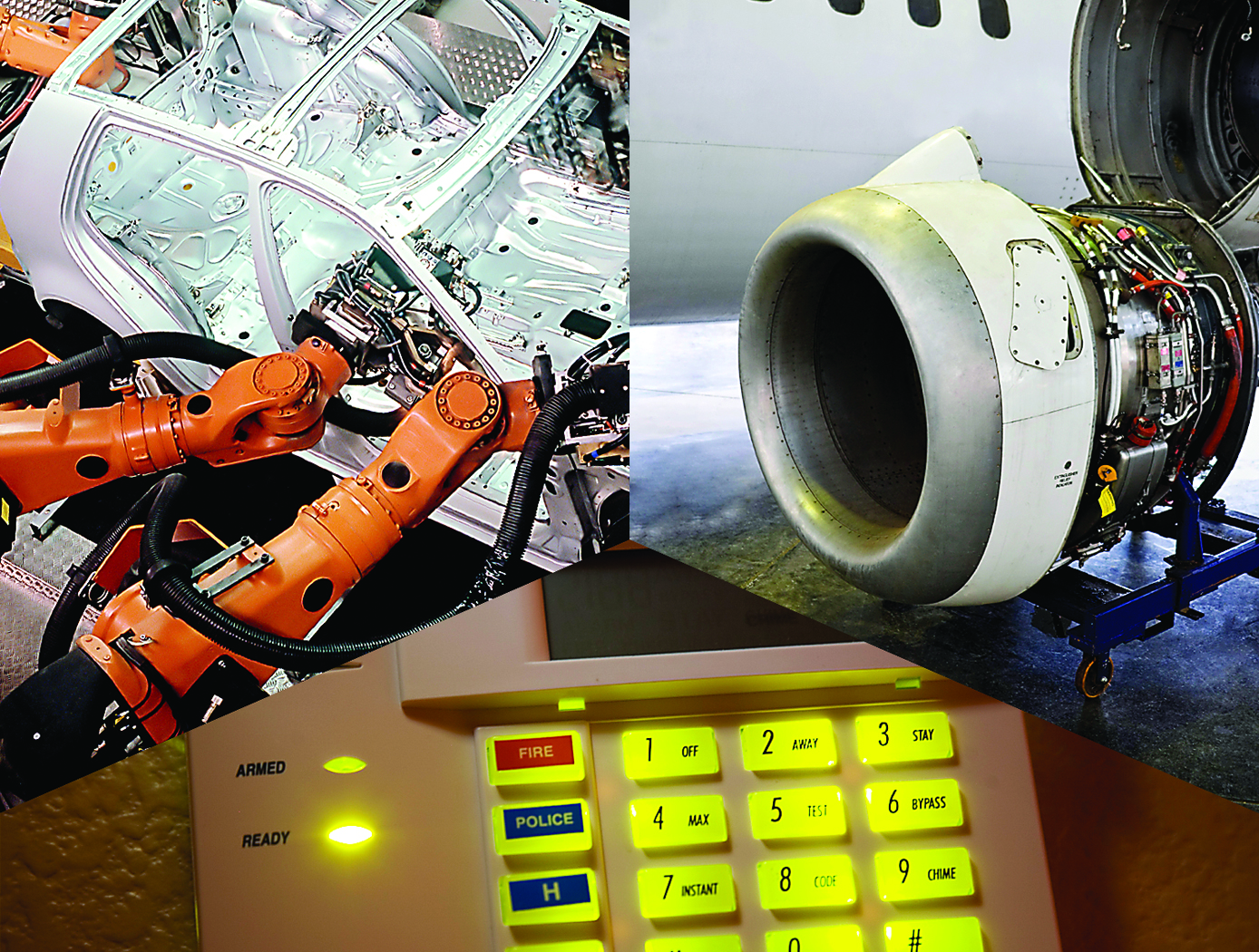
- Security systems - wireless keypads and motion detectors
- Aerospace - testing and monitoring
Similar Results

Lightning Mitigation and Damage Detection
The NASA technology can be used to protect tall structures from lightning strike damage. When a lightning leader propagates through the atmosphere in the vicinity of a tall structure, the lightning electromagnetic emissions generated from the moving electrical charge will impinge upon the tall structure before the actual charge attaches. As the lightning leader propagates closer to the tall structure, the radiated emissions at the tall structure will grow stronger. The SansEC sensor is designed to operate within the lightning radiated emission spectrum and thus is passively powered by the external oscillating magnetic field from the lightning itself. The sensor will resonate and generate its own oscillating magnetic and electric fields which have been demonstrated to influence lighting attachment and propagation.

Smart Skin for Composite Aircraft
When a lightning leader propagates through the atmosphere in the vicinity of an aircraft, the lightning electromagnetic emissions generated from the moving electrical charge will radiate the aircraft surface before the actual strike to the aircraft can occur. As the lightning leader propagates closer to the aircraft, the radiated emissions at the aircraft will grow stronger. By design, the frequency bandwidth of the lightning radiated is in the range for SansEC resonance. Hence the SansEC coil will be passively powered by the external oscillating magnetic field of the lightning radiated emission. The coil will resonate and generate its own oscillating magnetic and electric fields. These fields generate so-called Lorentz forces that influence the direction and
momentum of the lightning attachment and thereby deflect/spread where the strike entry and exit points/damage occurs on the aircraft.

Cord Tension Measurement Device (C-Gauge)
The C-Gauge is made of a 3D-printed aluminum body with strain gauges attached to the inner and outer walls of the connecting beam. The legs of the gauge attach firmly to the cord. When the cord is stretched, the tension in the cord goes through the legs and into the beam, causing it to bend. This bending creates a tension and compression stress in the bottom and top surface of the beam, respectively. The strain gauges capture the tension and compression, which are then used to determine the tension in the cord. The use of multiple strain gauges mitigates any torsion loading of the gauge and provides a direct measurement of the axial tension load of the cord.
The C-Gauge is a low-profile, non-invasive system that can be installed onto an existing cord in a system (e.g., the suspension, reefing, or riser lines in a parachute) without the need to remove or re-install the cord. It is small and lightweight and does not add stiffness or weight to the cord and thus does not affect the dynamics of the parachute or the structural response of the system. The C-Gauge can be scaled to larger and smaller sizes to measure larger and smaller load capabilities, dependent on the cord.
The C-Gauge is at a TRL 4 (component and/or breadboard validation in a laboratory environment) and it is now available for your company to license and develop into a commercial product. Please note that NASA does not manufacture products itself for commercial sale.

Electric Field Imaging System
The EFI imaging platform consists of a sensor array, processing equipment, and an output device. By registering voltage differences at multiple points within the sensor array, the EFI system can calculate the electrical potential at points removed from the sensor. Using techniques similar to computed tomography, the electrical potential data can be assembled into a three-dimension map of the magnitude and direction of electric fields. Since objects interact with electric fields differently based on their shape and dielectric properties, this electric field data can then be used to understand shape,
internal structure, and dielectric properties (e.g., impedance, resistance) of objects in three dimensions.
The EFI sensor can be used on its own to see electric fields or image electric fieldemitting objects near the sensor (e.g., to evaluate leakage from poorly shielded wires or casings). For evaluation of objects that do not produce an electric field, NASA has developed generator that emits a low-current, human-safe electrostatic field for snapshot evaluation of objects. Additionally, an alternative EFI system optimized to evaluate electric fields at significant distances (greater than 1 mile) is being developed for weather-related applications.

In Situ Wire Damage Detection and Rerouting System
The tester was designed to monitor electrical faults in either online or offline modes of operation. In the online mode, wires are monitored without disturbing their normal operation. A cable can be monitored several times per second in the offline mode, and once per second in the online mode. The online cable fault locator not only detects the occurrence of a fault, but also determines the type of fault (short/open/intermittent) and the location of the fault. This enables the detection of intermittent faults that can be repaired before they become serious problems. Since intermittent faults occur mainly during operations, a built-in memory device stores all relevant fault data. This data can be displayed in real time or retrieved later so maintenance and repairs can be completed without spending countless hours attempting to pinpoint the source of the problem.
Hardware and algorithms have also been developed to safely, efficiently, and autonomously transfer electrical power and data connectivity from an identified damaged/defective wire in a cable to an alternate wire path. This portion of the system consists of master and slave units that provide the diagnostic and rerouting capabilities. A test pulse generated by the master unit is sent down an active wire being monitored by the slave unit. When the slave unit detects the test pulse, it routes the pulse back to the master unit through a communication wire. When the master unit determines that a test pulse is not being returned, it designates that wire as faulty and reroutes the circuit to a spare wire.



