Search
PATENT PORTFOLIO

Lightweight Fiber Optic Sensors for Real-Time Monitoring of Structural Health
How It Works
The FOSS technology employs efficient, real-time, data driven algorithms for interpreting strain data. The fiber Bragg grating sensors respond to strain due to stress or pressure on the substrate. The sensors feed these strain measurements into the systems algorithms to determine shape, stress, temperature, pressure, strength, and operational load in real time.
Why It Is Better
Conventional strain gauges are heavy, bulky, spaced at distant intervals (which leads to lower resolution imaging), and unable to provide real-time measurements. Armstrong's system is virtually weightless, and thousands of sensors can be placed at quarter-inch intervals along an optical fiber the size of a human hair. Because these sensors can be placed at such close intervals and in previously inaccessible regions (for example, within bolted joints, embedded in a composite structure), the high-resolution strain measurements are more precise than ever before. The fiber optic sensors are non-intrusive and easy to install—thousands of sensors can be installed in less time than conventional strain sensors and the system is capable of processing information at the unprecedented rate of 100 samples per second. This critical, real-time monitoring capability enables an immediate and informed response in the event of an emergency and allows for precise, controlled monitoring to help avoid such scenarios.
For more information about the full portfolio of FOSS technologies, see DRC-TOPS-37 or visit https://technology-afrc.ndc.nasa.gov/featurestory/fiber-optic-sensing

Real-Time, High-Resolution Terrain Information in Computing-Constrained Environments
NASA Armstrong collaborated with the U.S. Air Force to develop algorithms that interpret highly encoded large area terrain maps with geographically user-defined error tolerances. A key feature of the software is its ability to locally decode and render DTMs in real time for a high-performance airplane that may need automatic course correction due to unexpected and dynamic events. Armstrong researchers are integrating the algorithms into a Global Elevation Data Adaptive Compression System (GEDACS) software package, which will enable customized maps from a variety of data sources.
How It Works
The DTM software achieves its high performance encoding and decoding processes using a unique combination of regular and semi-regular geometric tiling for optimal rendering of a requested map. This tiling allows the software to retain important slope information and continuously and accurately represent the terrain. Maps and decoding logic are integrated into an aircraft's existing onboard computing environment and can operate on a mobile device, an EFB, or flight control and avionics computer systems. Users can adjust the DTM encoding routines and error tolerances to suit evolving platform and mission requirements. Maps can be tailored to flight profiles of a wide range of aircraft, including fighter jets, UAVs, and general aviation aircraft.
The DTM and GEDACS software enable the encoding of global digital terrain data into a file size small enough to fit onto a tablet or other handheld/mobile device for next-generation ground collision avoidance. With improved digital terrain data, aircraft could attain better performance. The system monitors the ground approach and an aircraft's ability to maneuver by predicting several multidirectional escape trajectories, a feature that will be particularly advantageous to general aviation aircraft.
Why It Is Better
Conventional DTM encoding techniques used aboard high-performance aircraft typically achieve relatively low encoding process ratios. Also, the computational complexity of the decoding process can be high, making them unsuitable for the real-time constrained computing environments of high-performance aircraft. Implementation costs are also often prohibitive for general aviation aircraft. This software achieves its high encoding process ratio by intelligently interpreting its maps rather than requiring absolute retention of all data. For example, the DTM software notes the perimeter and depth of a mining pit but ignores contours that are irrelevant based on the climb and turn performance of a particular aircraft and therefore does not waste valuable computational resources. Through this type of intelligent processing, the software eliminates the need to maintain absolute retention of all data and achieves a much higher encoding process ratio than conventional terrain-mapping software. The resulting exceptional encoding process allows users to store a larger library of DTMs in one place, enabling comprehensive map coverage at all times. Additionally, the ability to selectively tailor resolution enables high-fidelity sections of terrain data to be incorporated seamlessly into a map.

Sensing Magnetic Fields
This technology is part of Armstrong's portfolio of fiber optic sensing technologies known as FOSS. The innovation leverages Armstrong's cutting edge work in this area, including its patented FBG interrogation system, which allows for a diverse set of engineering measurements in a single compact system. In addition to magnetic field, other measurements include structural shape and buckling modes, external loads, and cryogenic liquid level. The system and measurement technology is commercially available for research applications. In addition to capitalizing on the significant advancements in fiber optic and laser technologies that have been made to support the telecommunications industry, Armstrong has also partnered with UCLA's Active Materials Lab (AML) to tap their expertise in the field of magnetics.
For more information about the full portfolio of FOSS technologies, see DRC-TOPS-37 or visit https://technology-afrc.ndc.nasa.gov/featurestory/fiber-optic-sensing

Fiber Optic Sensing Technologies
The FOSS technology revolutionizes fiber optic sensing by using its innovative algorithms to calculate a range of useful parameters—any and all of which can be monitored simultaneously and in real time. FOSS also couples these cutting-edge algorithms with a high-speed, low-cost processing platform and interrogator to create a single, robust, stand-alone instrumentation system. The system distributes thousands of sensors in a vast network—much like the human body's nervous system—that provides valuable information.
How It Works
Fiber Bragg grating (FBG) sensors are embedded in an optical fiber at intervals as small as 0.25 inches, which is then attached to or integrated into the structure. An innovative, low-cost, temperature-tuned distributed feedback (DFB) laser with no moving parts interrogates the FBG sensors as they respond to changes in optical wavelength resulting from stress or pressure on the structure, sending the data to a processing system. Unique algorithms correlate optical response to displacement data, calculating the shape and movement of the optical fiber (and, by extension, the structure) in real time, without affecting the structure's intrinsic properties. The system uses these data to calculate additional parameters, displaying parameters such as 2D and 3D shape/position, temperature, liquid level, stiffness, strength, pressure, stress, and operational loads.
Why It Is Better
FOSS monitors strain, stresses, structural instabilities, temperature distributions, and a plethora of other engineering measurements in real time with a single instrumentation system weighing less than 10 pounds. FOSS can also discern between liquid and gas states in a tank or other container, providing accurate measurements at 0.25-inch intervals. Adaptive spatial resolution features enable faster signal processing and precision measurement only when and where it is needed, saving time and resources. As a result, FOSS lends itself well to long-term bandwidth-limited monitoring of structures that experience few variations but could be vulnerable as anomalies occur (e.g., a bridge stressed by strong wind gusts or an earthquake).
As a single example of the value FOSS can provide, consider oil and gas drilling applications. The FOSS technology could be incorporated into specialized drill heads to sense drill direction as well as temperature and pressure. Because FOSS accurately determines the drill shape, users can position the drill head exactly as needed. Temperature and pressure indicate the health of the drill. This type of strain and temperature monitoring could also be applied to sophisticated industrial bore scope usage in drilling and exploration.
For more information about the full portfolio of FOSS technologies, see visit https://technology-afrc.ndc.nasa.gov/featurestory/fiber-optic-sensing
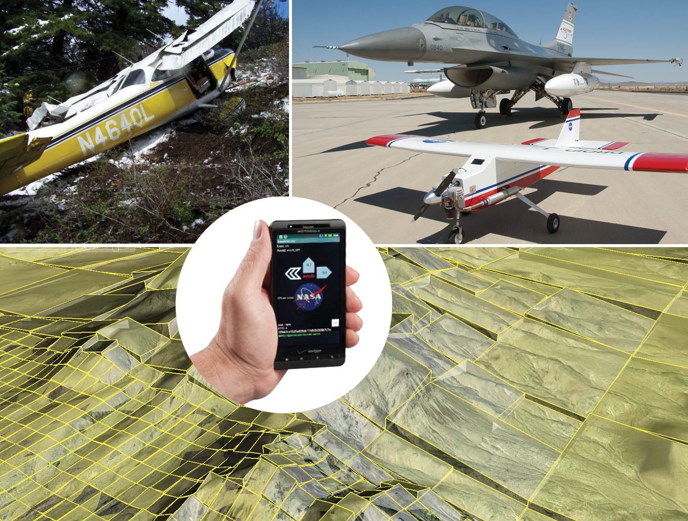
Improved Ground Collision Avoidance System
This critical safety tool can be used for a wider variety of aircraft, including general aviation, helicopters, and unmanned aerial vehicles (UAVs) while also improving performance in the fighter aircraft currently using this type of system.
Demonstrations/Testing
This improved approach to ground collision avoidance has been demonstrated on both small UAVs and a Cirrus SR22 while running the technology on a mobile device. These tests were performed to the prove feasibility of the app-based implementation of this technology. The testing also characterized the flight dynamics of the avoidance maneuvers for each platform, evaluated collision avoidance protection, and analyzed nuisance potential (i.e., the tendency to issue false warnings when the pilot does not consider ground impact to be imminent).
Armstrong's Work Toward an Automated Collision Avoidance System
Controlled flight into terrain (CFIT) remains a leading cause of fatalities in aviation, resulting in roughly 100 deaths each year in the United States alone. Although warning systems have virtually eliminated CFIT for large commercial air carriers, the problem still remains for fighter aircraft, helicopters, and GAA.
Innovations developed at NASAs Armstrong Flight Research Center are laying the foundation for a collision avoidance system that would automatically take control of an aircraft that is in danger of crashing into the ground and fly it—and the people inside—to safety. The technology relies on a navigation system to position the aircraft over a digital terrain elevation data base, algorithms to determine the potential and imminence of a collision, and an autopilot to avoid the potential collision. The system is designed not only to provide nuisance-free warnings to the pilot but also to take over when a pilot is disoriented or unable to control the aircraft.
The payoff from implementing the system, designed to operate with minimal modifications on a variety of aircraft, including military jets, UAVs, and GAA, could be billions of dollars and hundreds of lives and aircraft saved. Furthermore, the technology has the potential to be applied beyond aviation and could be adapted for use in any vehicle that has to avoid a collision threat, including aerospace satellites, automobiles, scientific research vehicles, and marine charting systems.

Shape Sensing Innovations Dramatically Improve Structural Design Tools
Armstrong's technologies provide a convenient way to calculate distributed deformed orientation angles—that is, roll, pitch, and yaw—as well as determine the deformed shape of an object in 3D space. Developed to facilitate monitoring and control of flexible aircraft designs when used in conjunction with Armstrong's multi-patented FOSS technology, these new tools improve shape-sensing accuracy for highly deformable structures such as bridges, wind turbines, robotic instruments, and much more. These tools also can be integrated into commercial fiber optic sensing systems.
How It Works
Researchers developed a technology that uses curved displacement transfer functions to determine 3D shape and calculate the operational load of a structure. It works by dividing the structure into multiple small domains, whose junctures match sensing stations, so that data is collected in a piecewise, nonlinear fashion. The innovation calculates structural stiffness (bending and torsion) and operational loads (bending moments, shear loads, and torques) in near real time.
The method tracks rotations and orientation by employing quaternion mathematical operations, a faster process than rotation matrices used in previous shape-sensing algorithms. The result is an algorithm that can track multiple angles—displacement, twist, and rotation—at the same time to enable curvilinear shaping sensing. Armstrong researchers have validated the method on the large-scale passive aeroelastic tailored (PAT) wing.
Why It Is Better
These new technologies advance the ability of fiber optic sensing systems to determine the shape and operational loads of nonlinear flexible surfaces. They can improve the structural integrity of a range of large structures—from buildings and bridges to ocean vessels and aircraft. These innovations reliably provide highly accurate critical information in real time, enabling corrective action to avert disasters.
For more information about the full portfolio of FOSS technologies, see DRC-TOPS-37 or visit https://technology-afrc.ndc.nasa.gov/featurestory/fiber-optic-sensing

Enhanced Fabrication Improves Temperature Sensing in Cryogenic Humid Environments
This technology was developed to improve Armstrong's multi-patented FOSS system, which has long been used to measure temperature and liquid levels in cryogenic environments. When the sensing system's fibers trapped humidity from the surrounding environment before their submersion into cryogenic liquids, the moisture adversely affected outputs. A new manufacturing process solves this problem, increasing reliability and accuracy not only of NASA's FOSS but also any fiber optic sensing system.
How It Works
Armstrong has developed a two-step process to assemble the sensors. First, the bare sensor fiber is inserted into an oven to expel all moisture from the fiber coating. Then, the moisture-free fiber is placed inside a humidity-controlled glove box to prevent it from absorbing any new moisture. While inside the glove box, the fiber is inserted into a loose barrier tubing that isolates the fiber yet is still thin enough to provide adequate thermal transfer. The tubing can be further purged with various gases while it is inside the glove box to provide additional moisture isolation.
This innovation is particularly useful for fiber optic systems that measure temperature and that identify any temperature stratifications within cryogenic liquids.
Why It Is Better
This process seals sensor fibers from environmental moisture, enabling fiber optic sensing systems to operate reliably in humid environments. The innovation eliminates erroneous readings that can occur due to moisture collection on the fiber sensors.
For more information about the full portfolio of FOSS technologies, see DRC-TOPS-37 or visit https://technology-afrc.ndc.nasa.gov/featurestory/fiber-optic-sensing

Compact, Temperature-Tuned OFDR Laser
Because OFDR-based fiber interrogation systems rely upon interferometry between sensors with respect to a unique reference length, the excitation source (laser) must lase at a single longitudinal mode (SLM). If the excitation source contains multiple modes, the resulting beat frequency becomes a super-position of the multiple frequencies caused by the modes; as a result, the sensor cannot be accurately defined in the Fourier domain. For OFDR systems with high sensing ranges, a continuous wavelength tunable laser must be used to accommodate the resonant wavelength shift of the fiber sensors due to environmental changes. External cavity lasers (ECLs) have been used due to their narrow linewidth and ability to lase at a SLM with no mode-hopping between steps. However, the mechanical complexity associated with tuning, susceptibility to vibration and shock, and high price point leave much to be desired.
To overcome the limitations of OFDR-based FOSS systems resulting from non-ideal excitation sources, NASA has developed a narrow linewidth solid-state laser based on the Distributed Feedback (DFB) laser. NASA’s laser is continuously tuned by manipulating the laser cavity’s temperature via a thermal-electric cooler feedback system. This continuous wavelength tuning generates a clean clock signal within an auxiliary interferometer, while the laser simultaneously interrogates multiple FBGs to produce a clean sensing interferometer. A Fourier domain spectrograph is used to show the unique frequency (i.e., location) of each FBG.
While NASA’s excitation source provides several performance advantages over conventional lasers used in OFDR, it is also highly compact and one eighth the cost of the ECLs traditionally used as excitation sources in OFDR-based systems. The laser has no moving parts, which also substantially improves system reliability.
Originally developed to demonstrate a low-cost interrogator for liquid level sensing in oil tanks, NASA’s compact, temperature-tuned OFDR laser can be applied wherever OFDR-based fiber optic sensing is desirable. Additional applications may include temperature distribution sensing, strain sensing, pressure sensing, and more.
NASA AFRC has strong subject matter expertise in fiber optic sensing systems, and has developed several patented technologies that are available for commercial licensing. For more information about the full portfolio of FOSS technologies, visit:
https://technology-afrc.ndc.nasa.gov/featurestory/fiber-optic-sensing

Streamlined Liquid Level Sensing Using Fiber Optics
Armstrong has developed a robust fiber optic–based sensing technology that offers extraordinary accuracy in liquid level measurements. The sensing system uses fiber optic Bragg sensors located along a single fiber optic cable. These sensors actively discern between the liquid and gas states along a continuous fiber and can accurately pinpoint the liquid level.
How It Works
The technology uses a resistive heater wire bundled with the optical fiber. The heater is pulsed to induce a local temperature change along the fiber, and the fiber Bragg grating data is used to monitor the subsequent cooling of the fiber. The length of fiber in the liquid cools more rapidly than the portion of the fiber in the gas above the liquid. The measurement system accurately establishes the location of this transition to within 1/4-inch.
Why It Is Better
Armstrong's liquid level sensing technology was originally developed to measure cryogenic liquid levels in rockets, and it represents a significant advancement in the state of the art in this application. Conventional methods for measuring cryogenic liquid levels rely on cryogenic diodes strategically placed along a rod or rack. The diodes are mounted in pre-selected, relatively widely spaced positions along the length of a rod; this configuration provides limited, imprecise data. Furthermore, each diode on the rod has two wires associated with it, which means a single system may require a large number of wires, making installation, connectivity, and instrumentation cumbersome.
Armstrong's novel technology provides liquid measurements with much greater precision, achieving measurements at 1/4-inch intervals. Furthermore, the streamlined system uses just two wires, which greatly simplifies installation and instrumentation. Due to its extraordinary accuracy and ease of use, Armstrong's measurement system offers important advantages for a wide range of applications beyond cryogenic liquids.
In Addition
Researchers have developed a new manufacturing process that improves the ability of fiber optic sensing systems to measure temperature and liquid levels when operating in humid environments. The process involves eliminating moisture from the optical fiber coating, then completing the sensor assembly within humidity-controlled conditions. The resulting sensor hardware provides precise and accurate measurements even when operating in a humid environment.
For more information about the full portfolio of FOSS technologies, see DRC-TOPS-37 or visit https://technology-afrc.ndc.nasa.gov/featurestory/fiber-optic-sensing
View more patents



