Search
aerospace
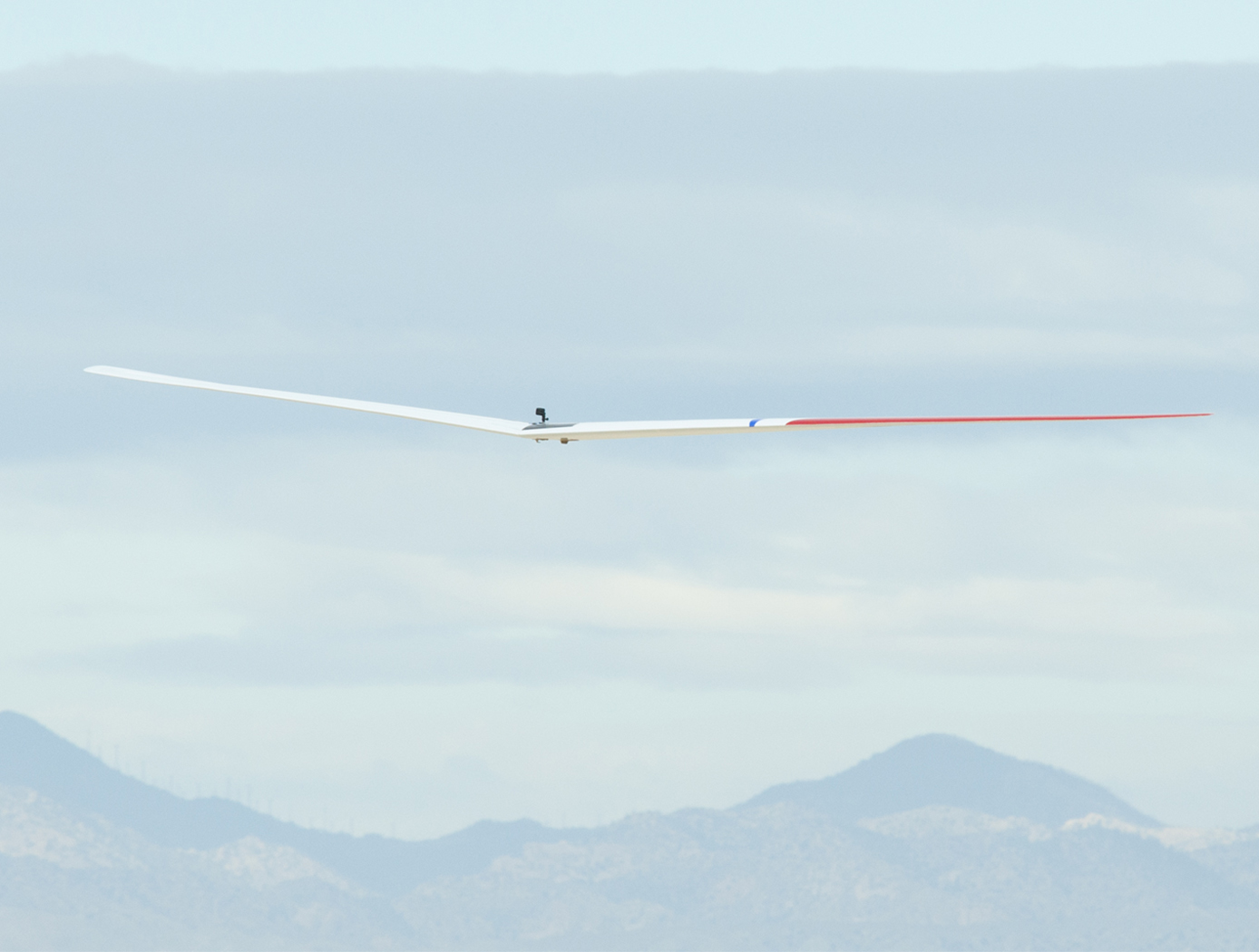
New Wing Design Exponentially Increases Total Aircraft Efficiency
Adverse yaw, present in current aircraft design, is the adverse horizontal movement around a vertical axis of an aircraft; the yaw opposes the direction of a turn. As an aircraft turns, differential drag of the left and right wings while banking contributes to aircraft yaw. Proverse yaw—yawing in the same direction as a turn—would optimize aircraft performance. Initial results from flight experiments at Armstrong demonstrated that this wing design unequivocally established proverse yaw. This wing design further reduces drag due to lift at the same time.
<strong>How It Works</strong>
The Armstrong team (supported by a large contingent of NASA Aeronautics Academy interns) built upon the 1933 research of the German engineer Ludwig Prandtl to design and validate a scale model of a non-elliptical loaded wing that reduces drag and increases efficiency.
The key to the innovation is reducing the drag of the wing through use of an alternative bell-shaped spanload, as opposed to the conventional elliptical spanload. To achieve the bell spanload, designers used a sharply tapered wing, with 12 percent less wing area than the comparable elliptical spanload wing. The new wing has 22 percent more span and 11 percent less area, resulting in an immediate 12 percent drag reduction.
Furthermore, using twist to achieve the bell spanload produces induced thrust at the wing tips, and this forward thrust increases when lift is increased at the wingtips for roll control. The result is that the aircraft rolls and yaws in the same direction as a turn, eliminating the need for a vertical tail. When combined with a blended-wing body, this approach maximizes aerodynamic performance, minimizes weight, and optimizes flight control.
<strong>Why It Is Better</strong>
Conventional aircraft make use of elliptical loaded wings to minimize drag. However, achieving aircraft stability and control in conventional elliptical wings produces a strong adverse yaw component in roll control (i.e., the aircraft will yaw the opposite direction with application of roll control). Therefore, a vertical tail or some other method of direct yaw control is required, such as split elevons for use as drag rudders. The use of elliptical wings also results in a suboptimal amount of structure to carry the integrated wing bending moment.
Adopting the bell-shaped spanload change results in an immediate 12 percent drag reduction. In addition, optimization of the overall aircraft configuration is projected to achieve additional significant overall performance increases.
aerospace
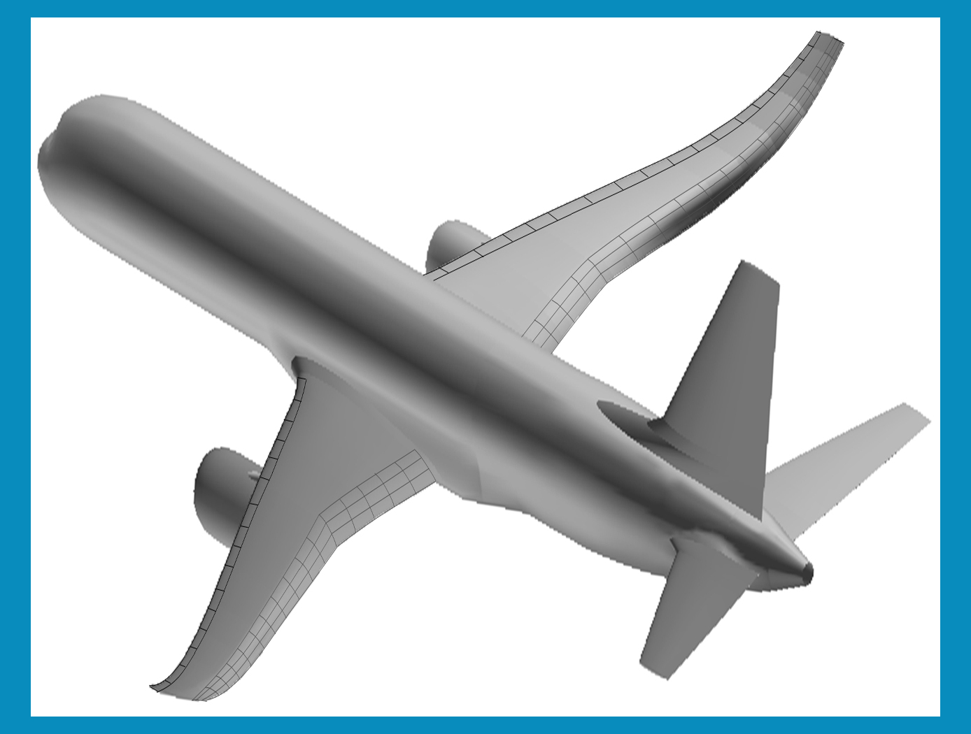
Green aviation - improved aerodynamic efficiency and less fuel burn
Currently, as fuel is burned, wing loading is reduced, thereby causing the wing shape to bend and twist. This wing-shape change causes the wings to be less aerodynamically efficient. This problem can be further exacerbated by modern high-aspect flexible wing design. Aircraft designers typically address the fuel efficiency goal by reducing aircraft weights, improving propulsion efficiency, and/or improving the aerodynamics of aircraft wings passively. In so doing, the potential drag penalty due to changes in the wing shapes still exists at off-design conditions. The unique or novel features of the new concepts are:
1. Variable camber flap provides the same lift capability for lower drag as compared to a conventional flap. The variable camber trailing edge flap (or leading edge slat) comprises multiple chord-wise segments (three or more) to form a cambered flap surface, and multiple span-wise segments to form a continuous trailing edge (or leading edge) curve with no gaps which could be prescribed by a mathematical function or the equivalent with boundary conditions enforced at the end points to minimize tip vortices
2. Continuous trailing edge flap (or leading edge slat) provides a continuously curved trailing edge (or leading edge) with no gaps to minimize vortices that can lead to an increase in drag.
3. The active wing-shaping control method utilizes the novel flap (or slat) concept described herein to change a wing shape to improve aerodynamic efficiency by optimizing span-wise aerodynamics.
4. An aeroelastic wing shaping method for analyzing wing deflection shape under aerodynamic loading is used in a wing-control algorithm to compute a desired command for the flap-actuation system to drive the present flap (or slat) system to the correct position for wing shaping.
optics
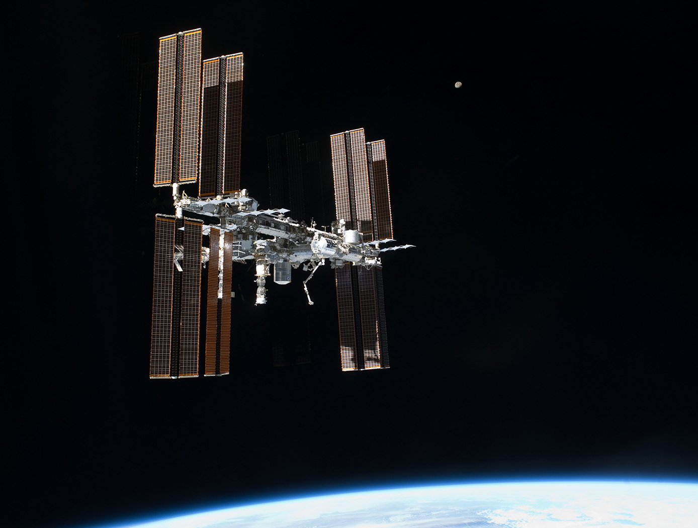
Spatial Standard Observer (SSO)
The Spatial Standard Observer (SSO) provides a tool that allows measurement of the visibility of an element, or visual discriminability of two elements. The device may be used whenever it is necessary to measure or specify visibility or visual intensity. The SSO is based on a model of human vision, and has been calibrated by an extensive set of human test data. The SSO operates on a digital image or a pair of digital images. It computes a numerical measure of the perceptual strength of the single image, or of the visible difference between the two images. The visibility measurements are provided in units of Just Noticeable Differences (JND), a standard measure of perceptual intensity.
A target that is just visible has a measure of 1 JND. The SSO will be useful in a wide variety of applications, most notably in the inspection of displays during the manufacturing process. It is also useful in for evaluating vision from unpiloted aerial vehicles (UAV) predicting visibility of UAVs from other aircraft, from the control tower of aircraft on runways, measuring visibility of damage to aircraft and to the shuttle orbiter, evaluation of legibility of text, icons or symbols in a graphical user interface, specification of camera and display resolution, inspection of displays during the manufacturing process, estimation of the quality of compressed digital video, and predicting outcomes of corrective laser eye surgery.
Aerospace
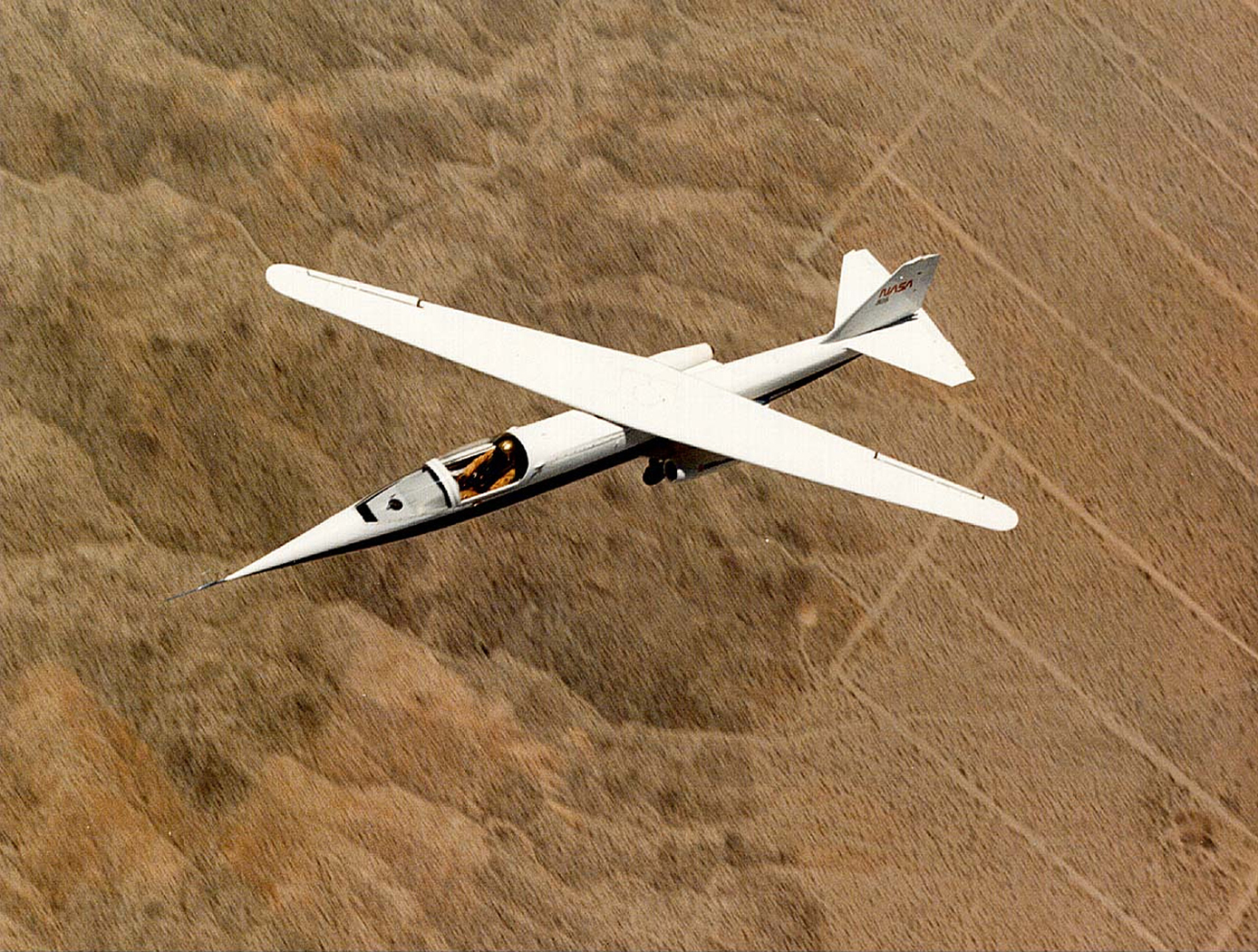
Variable Geometry Aircraft Wing Supported By Struts and/or Trusses
This innovation utilizes a strut/truss-braced oblique variable-sweep wing mounted on a constant cross-section geometry fuselage. The combination of the strut/truss-bracing with the oblique wing greatly reduces the structural and weight penalties previously associated with unbraced oblique wing configurations while maintaining the oblique wings improved aerodynamic performance. Strut/truss bracing helps to further reduce the wing weight, and can be used to automatically align wing-mounted engines with the oncoming flow. The synergistic combination of these design elements provides the aircraft with a wide and efficient cruise speed range when the wing is at intermediate sweep positions, and superior low speed performance when the wing is unswept. The wing could remain aligned during taxiing, reducing the chance of collisions with other taxiing aircraft. This wide speed envelope provides future air traffic systems with additional flexibility when scheduling efficient arrivals and departures. The improved climb performance of the straight wing reduces the neighborhood noise footprint of the aircraft as it departs the airport. Efficient aircraft designs are increasingly desired in order to support the continued growth of the air transportation industry. Continued expansion of this vital mode of transportation is threatened by ever-increasing challenges in emissions, noise, and fuel efficiency.
aerospace
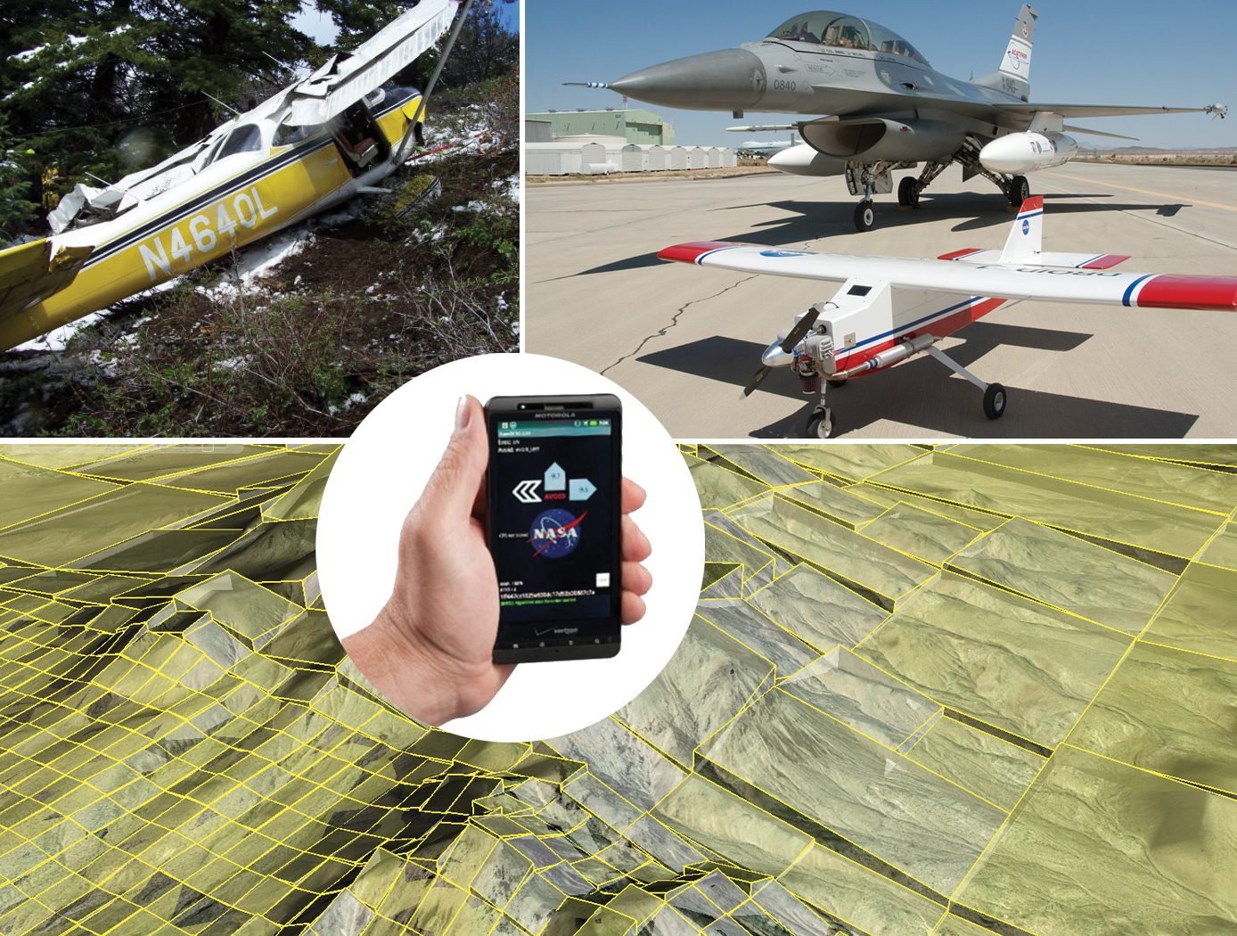
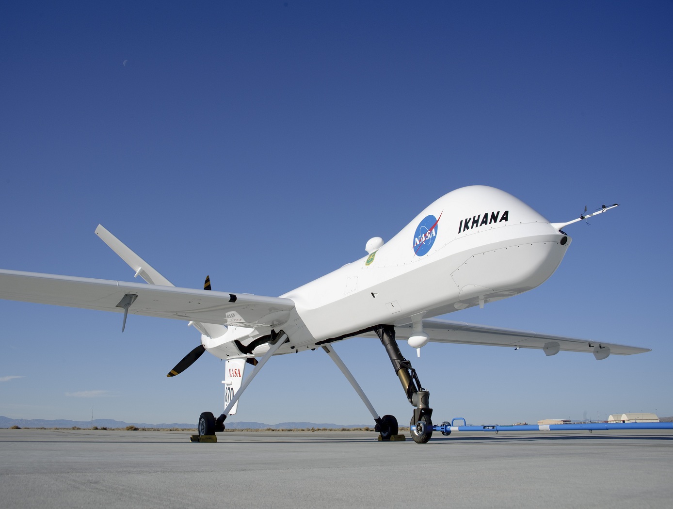
Improved Ground Collision Avoidance System
This critical safety tool can be used for a wider variety of aircraft, including general aviation, helicopters, and unmanned aerial vehicles (UAVs) while also improving performance in the fighter aircraft currently using this type of system.
<strong>Demonstrations/Testing</strong>
This improved approach to ground collision avoidance has been demonstrated on both small UAVs and a Cirrus SR22 while running the technology on a mobile device. These tests were performed to the prove feasibility of the app-based implementation of this technology. The testing also characterized the flight dynamics of the avoidance maneuvers for each platform, evaluated collision avoidance protection, and analyzed nuisance potential (i.e., the tendency to issue false warnings when the pilot does not consider ground impact to be imminent).
<strong>Armstrong's Work Toward an Automated Collision Avoidance System</strong>
Controlled flight into terrain (CFIT) remains a leading cause of fatalities in aviation, resulting in roughly 100 deaths each year in the United States alone. Although warning systems have virtually eliminated CFIT for large commercial air carriers, the problem still remains for fighter aircraft, helicopters, and GAA.
Innovations developed at NASAs Armstrong Flight Research Center are laying the foundation for a collision avoidance system that would automatically take control of an aircraft that is in danger of crashing into the ground and fly it—and the people inside—to safety. The technology relies on a navigation system to position the aircraft over a digital terrain elevation data base, algorithms to determine the potential and imminence of a collision, and an autopilot to avoid the potential collision. The system is designed not only to provide nuisance-free warnings to the pilot but also to take over when a pilot is disoriented or unable to control the aircraft.
The payoff from implementing the system, designed to operate with minimal modifications on a variety of aircraft, including military jets, UAVs, and GAA, could be billions of dollars and hundreds of lives and aircraft saved. Furthermore, the technology has the potential to be applied beyond aviation and could be adapted for use in any vehicle that has to avoid a collision threat, including aerospace satellites, automobiles, scientific research vehicles, and marine charting systems.
Aerospace
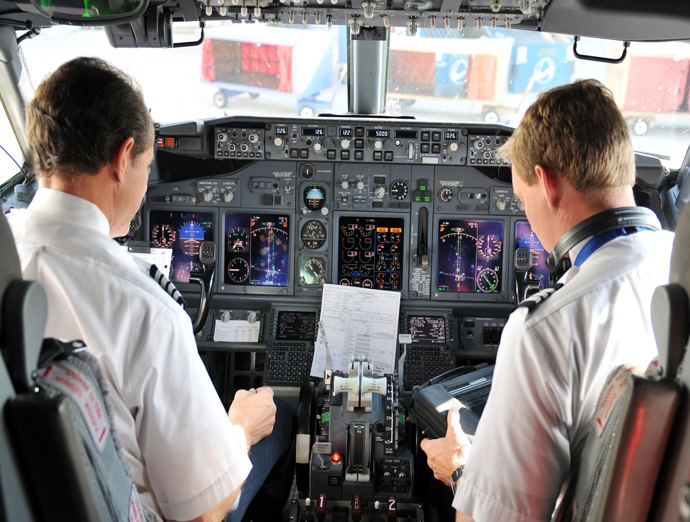
Foot Pedal Controller
The Foot Pedal Controller enables an operator of a spacecraft, aircraft, or watercraft, or a simulation of one in a video game, to control all translational and rotational movement using two foot pedals. This novel technology allows control across all six degrees of freedom, unlike any technology on the market. The components of the technology are a support structure, a left foot pedal, a right foot pedal, and supporting electronics. The Foot Pedal Controller is intuitive, easy to learn, and has ergonomic features that accommodate and stabilize the operator's feet. A working prototype is available to demonstrate key technology features to potential licensees.
The Foot Pedal Controller technology could be used in designs for the flight deck of the future, video game controls, drone operations and flight simulators. This technology can be useful in any application where it is preferred or desirable to use the feet to control motion rather than using the hands. A potential market could be foot control of equipment by people with arm or hand disabilities. A unique aspect of the innovation is the consideration of natural foot mechanics in the design and placement of the sensors and actuators to reduce operator fatigue. The axes of rotation of the Controller align with the joints of the foot so the foot moves naturally to control the movement of the craft. NASA seeks collaborations with companies interested in licensing and partnering to further develop and commercialize the technology.
Robotics Automation and Control

Adaptive wind estimation for small unmanned aerial systems using motion data
The technology presents an on-board estimation, navigation and control architecture for multi-rotor drones flying in an urban environment. It consists of adaptive algorithms to estimate the vehicle's aerodynamic drag coefficients with respect to still air and urban wind components along the flight trajectory, with guaranteed fast and reliable convergence to the true values. Navigation algorithms generate feasible trajectories between given way-points that take into account the estimated wind. Control algorithms track the generated trajectories as long as the vehicle retains a sufficient number of functioning rotors that are capable of compensating for the estimated wind. The technology provides a method of measuring wind profiles on a drone using existing motion sensors, like the inertial measurement unit (IMU), rate gyroscope, etc., that are observably necessary for any drone to operate. The algorithms are used to estimate wind around the drone. They can be used for stability or trajectory calculations, and are adaptable for use with any UAV regardless of the knowledge of weight and inertia. They further provide real-time calculations without additional sensors. The estimation method is implemented using onboard computing power. It rapidly converges to true values, is computationally inexpensive, and does not require any specific hardware or specific vehicle maneuvers for the convergence. All components of this on-board system are computationally effective and are intended for a real time implementation. The method's software is developed in a Matlab/Simulink environment, and has executable versions, which are suitable for majority of existing onboard controllers. The algorithms were tested in simulations.
power generation and storage
High-Efficiency Solar Cell
This NASA Glenn innovation is a novel multi-junction photovoltaic cell constructed using selenium as a bonding material sandwiched between a thin film multi-junction wafer and a silicon substrate wafer, enabling higher efficiencies. A multi-junction photovoltaic cell differs from a single junction cell in that it has multiple sub-cells (p-n junctions) and can convert more of the sun's energy into electricity as the light passes through each layer. To further improve the efficiencies, this cell has three junctions, where the top wafer is made from high solar energy absorbing materials that form a two-junction cell made from the III-V semiconductor family, and the bottom substrate remains as a simple silicon wafer. The selenium interlayer is applied between the top and bottom wafers, then pressure annealed at 221°C (the melting temperature of selenium), then cooled. The selenium interlayer acts as a connective layer between the top cell that absorbs the short-wavelength light and the bottom silicon-based cell that absorbs the longer wavelengths. The three-junction solar cell manufactured using selenium as the transparent interlayer has a higher efficiency, converting more than twice the energy into electricity than traditional cells. To obtain even higher efficiencies of over 40%, both the top and bottom layers can be multi-junction solar cells with the selenium layer sandwiched in between. The resultant high performance multi-junction photovoltaic cell with the selenium interlayer provides more power per unit area while utilizing a low-cost silicon-based substrate. This unprecedented combination of increased efficiency and cost savings has considerable commercial potential.
This is an early-stage technology requiring additional development. Glenn welcomes co-development opportunities.
information technology and software
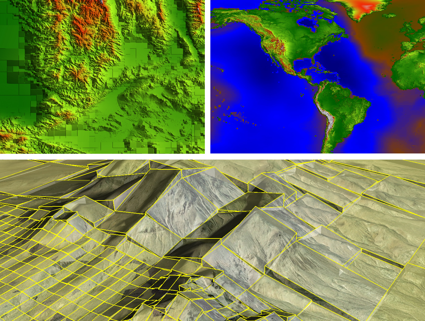
Real-Time, High-Resolution Terrain Information in Computing-Constrained Environments
NASA Armstrong collaborated with the U.S. Air Force to develop algorithms that interpret highly encoded large area terrain maps with geographically user-defined error tolerances. A key feature of the software is its ability to locally decode and render DTMs in real time for a high-performance airplane that may need automatic course correction due to unexpected and dynamic events. Armstrong researchers are integrating the algorithms into a Global Elevation Data Adaptive Compression System (GEDACS) software package, which will enable customized maps from a variety of data sources.
<strong>How It Works</strong>
The DTM software achieves its high performance encoding and decoding processes using a unique combination of regular and semi-regular geometric tiling for optimal rendering of a requested map. This tiling allows the software to retain important slope information and continuously and accurately represent the terrain. Maps and decoding logic are integrated into an aircraft's existing onboard computing environment and can operate on a mobile device, an EFB, or flight control and avionics computer systems. Users can adjust the DTM encoding routines and error tolerances to suit evolving platform and mission requirements. Maps can be tailored to flight profiles of a wide range of aircraft, including fighter jets, UAVs, and general aviation aircraft.
The DTM and GEDACS software enable the encoding of global digital terrain data into a file size small enough to fit onto a tablet or other handheld/mobile device for next-generation ground collision avoidance. With improved digital terrain data, aircraft could attain better performance. The system monitors the ground approach and an aircraft's ability to maneuver by predicting several multidirectional escape trajectories, a feature that will be particularly advantageous to general aviation aircraft.
<strong>Why It Is Better</strong>
Conventional DTM encoding techniques used aboard high-performance aircraft typically achieve relatively low encoding process ratios. Also, the computational complexity of the decoding process can be high, making them unsuitable for the real-time constrained computing environments of high-performance aircraft. Implementation costs are also often prohibitive for general aviation aircraft. This software achieves its high encoding process ratio by intelligently interpreting its maps rather than requiring absolute retention of all data. For example, the DTM software notes the perimeter and depth of a mining pit but ignores contours that are irrelevant based on the climb and turn performance of a particular aircraft and therefore does not waste valuable computational resources. Through this type of intelligent processing, the software eliminates the need to maintain absolute retention of all data and achieves a much higher encoding process ratio than conventional terrain-mapping software. The resulting exceptional encoding process allows users to store a larger library of DTMs in one place, enabling comprehensive map coverage at all times. Additionally, the ability to selectively tailor resolution enables high-fidelity sections of terrain data to be incorporated seamlessly into a map.
sensors

Super Resolution 3D Flash LIDAR
This suite of technologies includes a method, algorithms, and computer processing techniques to provide for image photometric correction and resolution enhancement at video rates (30 frames per second). This 3D (2D spatial and range) resolution enhancement uses the spatial and range information contained in each image frame, in conjunction with a sequence of overlapping or persistent images, to simultaneously enhance the spatial resolution and range and photometric accuracies. In other words, the technologies allows for generating an elevation (3D) map of a targeted area (e.g., terrain) with much enhanced resolution by blending consecutive camera image frames. The degree of image resolution enhancement increases with the number of acquired frames.

