Search
Instrumentation

Reconfigurable Local Oscillator for Coherent Optical Detection
The innovation expands the range of signals that coherent optical receivers can detect. Unlike traditional systems with fixed LOs, this approach allows real-time adjustments to an LO’s properties, such as frequency, phase, polarization, amplitude, spatial mode, or timing, to better match incoming signals. These adjustments improve measurement accuracy and signal recovery in various scenarios, such as shifting heterodyne frequencies into the receiver’s bandwidth or adapting to different signal polarizations. The innovation lies in the ability to switch an LO's configurations on the fly using technologies like fiber-optic or integrated photonic switches, as well as other methods like optical modulation or tunable delay lines. This dynamic capability allows coherent receivers to switch seamlessly between range-Doppler and Doppler-only modes. As a result, a single system can track both nearby, slow-moving targets and distant, high-velocity objects (up to 20+ km/s) while operating with a compact, low-speed receiver (<1 GHz). This versatility significantly enhances the performance and adaptability of advanced optical sensing and communication systems.
While initially developed for NASA’s Navigation Doppler LiDAR project, this invention can support advanced signal detection applications across several industries, including optical communications, aerospace, structural health monitoring, and autonomous vehicles. By enabling real-time reconfiguration, the invention offers improved signal recovery, enhanced sensitivity, and broader system adaptability for challenging detection environments. The technology has gone through prototype development and is currently at TRL 3 (proof-of-concept), and the reconfigured LO is available for patent licensing.
Communications

Optical Transceiver Method of QKD Encryption Suite of Technologies
The core of the technology is the SAW division de-multiplexing method (LEW-19920-1). It uses a commercially available double-clad fiber optic cable with a 9um core and a 105um first cladding. By optimizing the wavelengths of the QKD photon and data transmission, a single focusing lens can create a diffraction pattern that directs the QKD photons to the 9um core and the data signal to the 105um secondary core.
Key components of the system include:
• SOA Driver With Wideband Current Control (LEW-19913-1): This device allows a semiconductor optical amplifier (SOA) or laser to be driven with an arbitrary current at a rate of over 100 MHz. This enables the rapid generation of sub-nanosecond laser pulses with one of four polarization states, which is necessary for QKD.
• Random Bit Generator with Linear Feedback Shift Register LFSR Scrambler (LEW-20058-1): This device produces random bits by combining the output of a noise source with a pseudorandom bitstream from the LFSR. This allows a random basis set to be generated on demand for a polarization modulator.
• Variable-length quantum key conversion (LEW-20224-1): Since QKD operations produce keys of varying lengths, a strategy was developed to "digest" these raw keys using a hash function, such as SHAKE256. This process generates a fixed-length output that is useful for symmetric encryption schemes like AES256.
• The system also incorporates a Discretization Algorithm for Numerical Wave Optics Simulations (LEW-20119-1), which can accurately model the effects of atmospheric turbulence on the propagating optical beam.
Sensors
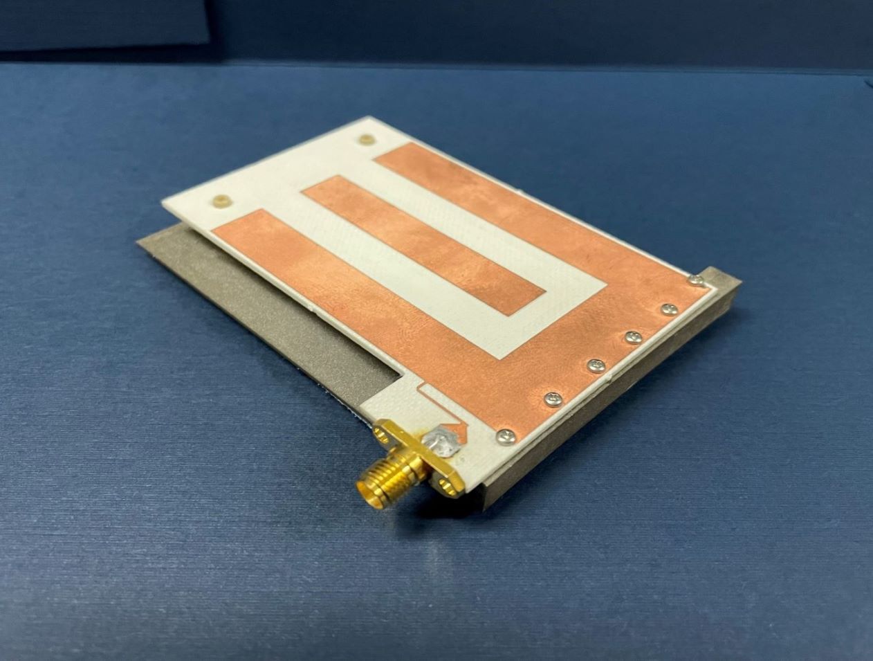
Low Mass Antenna Boosts RFID Device Performance
NASA’s HYDRA system enables a new approach in routing the RFID signal, greatly increasing extensibility and the number of antennas that can be served by a single reader. However, increasing the number of antennas in any environment is often undesirable unless the antenna size is inconspicuous. Basing this RFID dual mode antenna on a quarter-wavelength structure allows it to be smaller than an antenna designed for half-wavelength structure, reducing overall mass.
NASA’s RFID dual mode antenna is enabled by utilizing two different types of resonance modes – a “slot” mode and a microstrip “patch” mode. An innovative feed architecture allows for coupling from the RFID reader into both modes, with the impedance of each mode approximately equal at respective resonant frequencies. The antenna is designed such that each mode resonates at a different portion of the operating bandwidth, and further with each mode radiating an orthogonal polarization to the other. Frequency-hopping RFID protocols, used in conjunction with this antenna, result in the polarization diversity required for readers to reliably communicate with arbitrarily oriented RFID tags.
Numerous commercial applications exist for this RFID dual mode antenna. Examples may include usage in a multiple antenna architecture that is connected to a single reader in an open-air region, in a small, enclosed region such as a cabinet drawer, or through a combination of open and closed regions.
This RFID dual mode antenna has a technology readiness level (TRL) 7 (system prototype demonstrated in an operational environment) and is now available for patent licensing. Please note that NASA does not manufacture products itself for commercial sale.

