Search
instrumentation
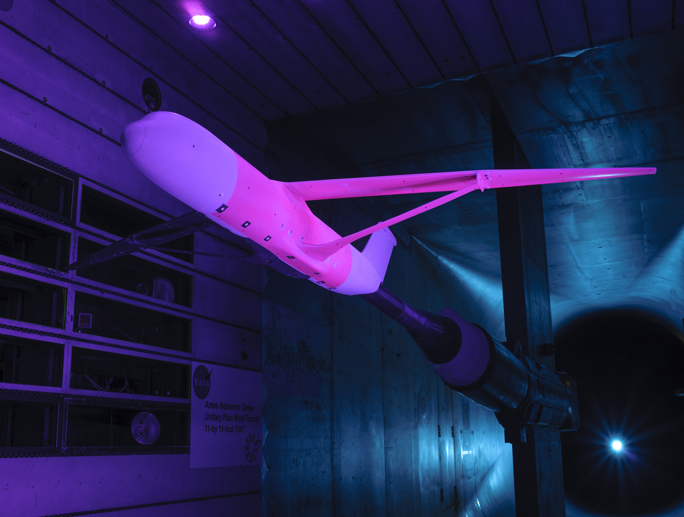
Calculation of Unsteady Aerodynamic Loads Using Fast-Response Pressure-Sensitive Paint (PSP)
Traditionally, unsteady pressure transducers have been the instrumentation of choice for investigating unsteady flow phenomena which can be time-consuming and expensive. The ability to measure and compute these flows has been a long-term challenge for aerospace vehicle designers and manufacturers. Results using only the pressure transducers are prone to inaccuracies, providing overly conservative load predictions in some cases and underestimating load predictions in other areas depending on the flow characteristics. NASA Ames has developed a new state-of-the-art method for measuring fluctuating aerodynamic-induced pressures on wind tunnel models using unsteady Pressure Sensitive Paint (uPSP). The technology couples recent advances in high-speed cameras, high-powered energy sources, and fast response pressure-sensitive paint. The unsteady pressure-sensitive paint (uPSP) technique has emerged as a powerful tool to measure flow, enabling time-resolved measurements of unsteady pressure fluctuations within a dense grid of spatial points on a wind tunnel model. The invention includes details surrounding uPSP processing. This technique enables time-resolved measurements of unsteady pressure fluctuations within a dense grid of spatial points representing the wind tunnel model. Since uPSP is applied by a spray gun, it is continuously distributed. With this approach, if the model geometry can be painted, viewed from a camera, and excited by a lamp source, uPSP data can be collected. Unsteady PSP (uPSP) has the ability to determine more accurate integrated unsteady loads.
sensors
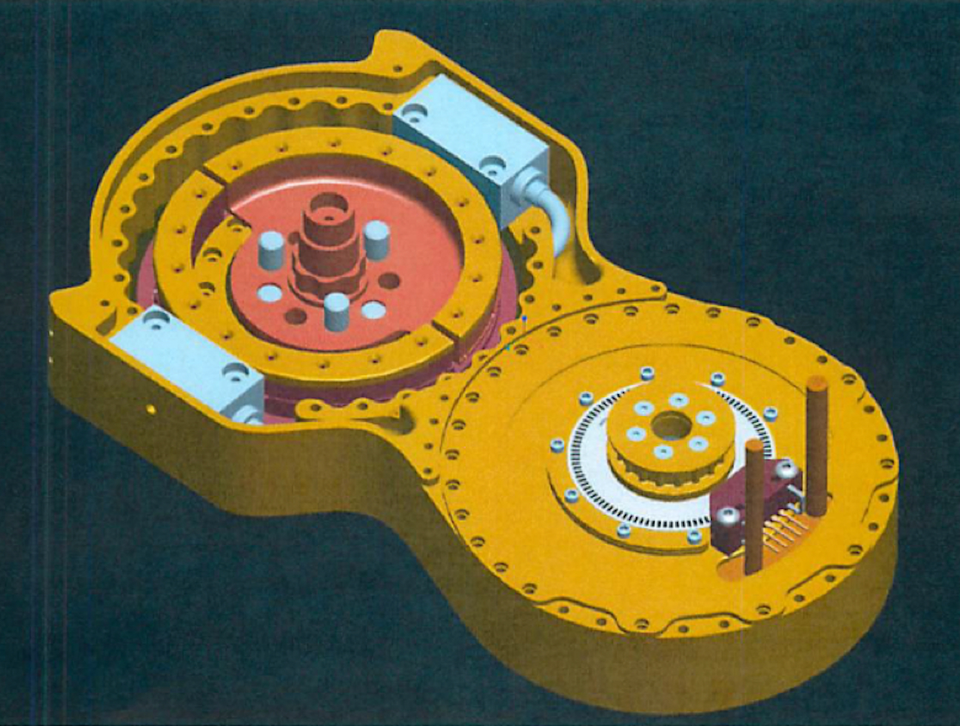
Split-Ring Torque Sensor
The SRTS enables measurement of position, velocity, and torque of a rotating system (e.g., actuator, motor, crankshaft, rotor, etc.) using two optical sensors and a single, custom-designed split-ring rather than the standard dual-ringed systems commonly used for similar applications. The split-ring is comprised of two structural arcs positioned in a concentric, coplanar relationship, wherein each arc is attached to a component capable of rotation (e.g., a lower leg and upper leg, where the SRTS acts as a knee). The two arcs contain indications or codes on their outer surfaces that are read by the optical sensors to determine the relative deflection of the structural arcs as they rotate.
The SRTS configuration discussed above is limited to 180-degree applications. The addition of a third structural arc and a third optical reader, however, would enable 360-degree functionality.
Tests have shown the SRTS has a high degree of tolerance to temperature differences and provides higher resolution measurements than competing technologies.

