Digital Beamforming Interferometry
optics
Digital Beamforming Interferometry (GSC-TOPS-22)
Dividing a single antenna into two antennas
Overview
Synthetic Aperture Radar (SAR) is a sophisticated form of radar that implements a single antenna to successfully scan a target area, store the received signals, and coherently process the signals to resolve elements in an image of the target area. Interferometric SAR (InSAR) uses two or more SAR images to generate three dimensional maps of surface deformation or digital elevation using phase difference information. InSAR is commonly implemented with SAR systems in a repeat pass platform configuration where two SAR images are generated during each of the passes, and an interferogram between the two images provides the desired "height" measurement, or in a single pass configuration where the SAR system uses two separate antennas are used to generate the interferogram.
NASA Goddard Space Flight Center has developed a new approach that uses a single phased array antenna and a single pass configuration to generate interferograms.
The Technology
NASA Goddard Space Flight Center (GSFC) has developed a new approach that uses a single phased array antenna and a single pass configuration to generate interferograms, known as Digital Beamforming Interferometry. A digital beamforming radar system allows the implementation of non-conventional radar techniques, known as Digital Beamforming Synthetic Aperture Radar Multi-mode Operation (DBSAR).
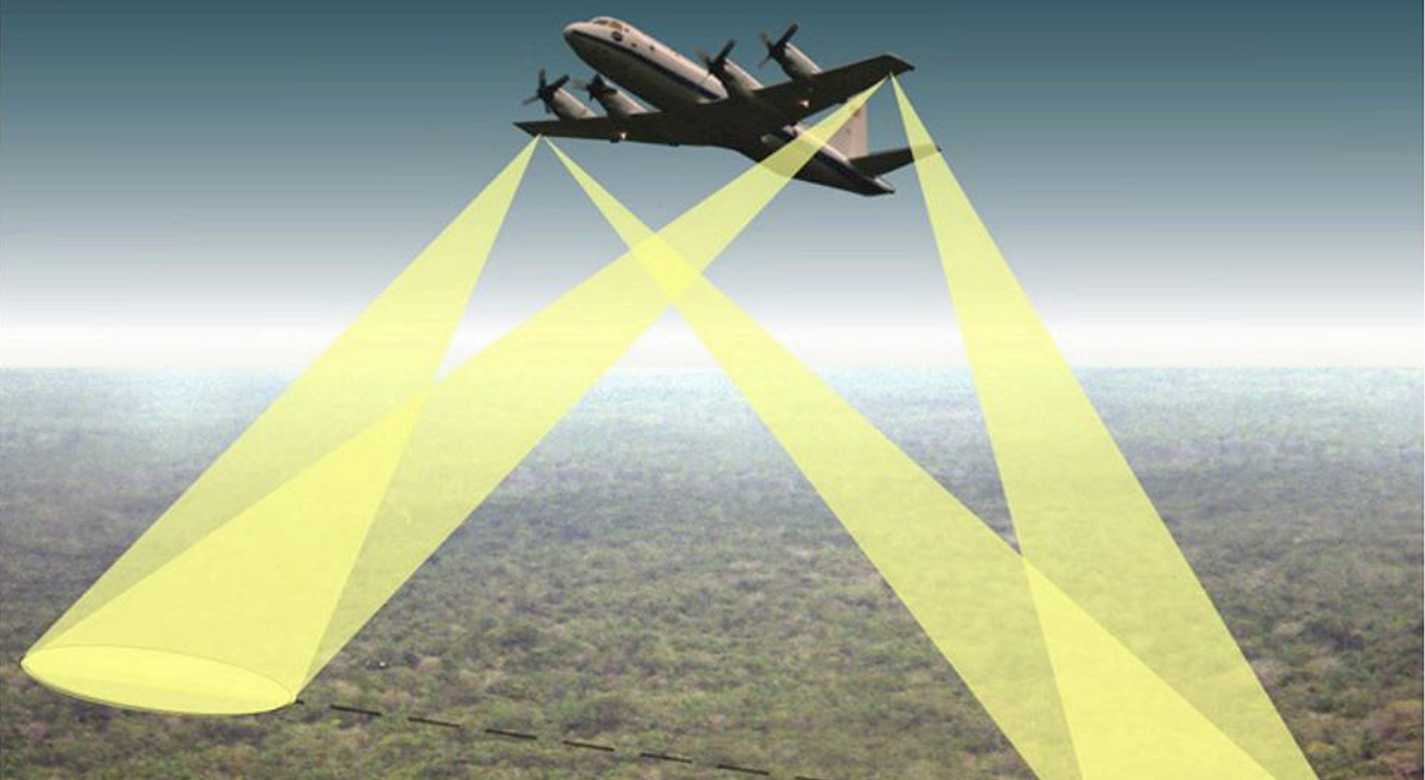
DBSAR is an L-Band airborne radar that combines advanced radar technology with the ability to implement multimode remote sensing techniques, including several variations of SAR, scatterometry over multiple beams, and an altimeter mode. The Multiple channel data acquired with a digital beamformer systems allows the synthesis of beams over separate areas of the antenna, effectively dividing the single antenna into two antennas. The InSAR technique is then achieved by generating interferograms from images collected with each of the antennas. Since the technique is performed on the data, it allows for synthesizing beams in different directions (or look angles) and performs interferometry over large areas.
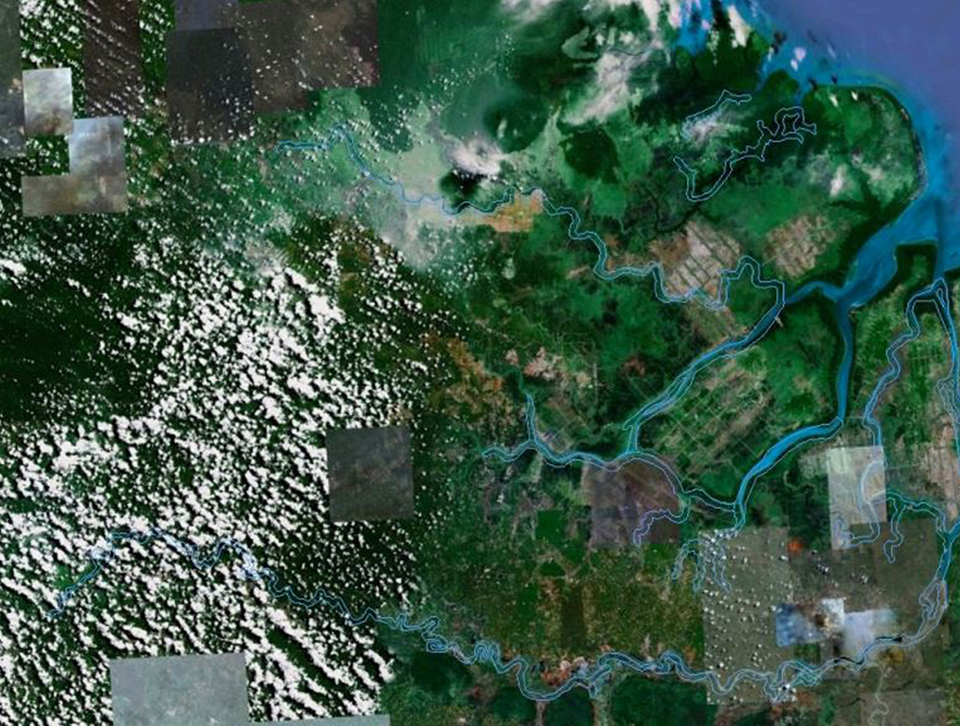
Digital Beamforming Interferometry has potential in many areas of radar applications. For example, NASA GSFC innovators developed the first P-Band Digital Beamforming Polarimetric Interferometric SAR Instrument to measure ecosystem structure, biomass, and surface water.


Benefits
- Simple design: reduces complexity inherent in typical systems
- Powerful and Extensive: capable of fine resolution measurements
- Doubles coverage area: able to synthesize beams on both sides of the track
- Effectively turns one nadir looking antenna into two
Applications
- Many areas of radar applications
- Enables InSAR measurements using single antenna radars
Similar Results

Concept Development for Advanced Spaceborne Synthetic Aperture Radar
The current innovation utilizes heritage flight proven L-band Digital Beamforming Synthetic Aperture Radar (DBSAR) in conjunction with a new P-Band Digital beamforming Polarimetric and Interferometric EcoSAR (ESTO IIP) architecture. The system employs digital beamforming (DBF) and reconfigurable hardware to provide advanced radar capabilities not possible with conventional radar instruments. The SAR is operated without the use of a slewing antenna allowing the single radar system to provide polarimetric imaging, interferometry, and altimetry or scatterometry data types. The SAR is also capable of Sweep-SAR, simultaneous SAR/GNSS-R , and simultaneous active/passive techniques.
This system has an increased coverage area and can rapidly image large areas of the surface using the simultaneous left/right imaging. The resulting images maintain their full resolution and allows for faster full coverage mapping

Dual-Polarized, Wideband, Lightweight P-band Antenna Element and Array
The P-band antenna array is built from rows and columns of antenna elements for the purpose of allowing beam steering up to the maximum desirable angle without incurring grating lobes in the radiation patterns. For flexible mission planning, a large array can be built from several of the small, panel-like elements. The elements are deployable from a folded or stacked stowed configuration during launch, arranged side by side during operation. Each antenna element is itself a fully functional small antenna array. The number of panels can be chosen as dictated by the mission objectives and budget.
Three geometries were designed and tested. Geometry 1 features non-planar metal structures with minimal dielectric support, where the back cavity is closed. Geometry 2 features non-planar metal structures with minimal composite sheet dielectric support, but with an open cavity. Both geometries avoid large flat sheets, which are vulnerable to bending, thereby increasing the mechanical stiffness of the structure while using only thin sheet metal and maintaining an exceptionally low mass-to-size ratio. Geometry 3 features planar metal structures, with sandwich composite dielectric support and an open cavity. While it does not benefit from the mechanical stiffness utilized in non-planar designs, the planar sandwich structure increase robustness and reduces the cost of fabrication. All element geometries have wideband capabilities and are dual polarized.
Although designed for space and planetary exploration, the P-band antenna is also valuable for various terrestrial use cases. The P-band antenna array is at technology readiness level (TRL) 5 (component and/or breadboard validation in relevant environment) and is available for patent licensing.

Waveguide-based Dielectric and Magnetic Property Measurement
This NASA invention utilizes a simple waveguide-based measurement system to determine the complex dielectric permittivity and magnetic permeability of arbitrary-shaped planetary rock samples. The system operates at L-band frequencies (~1 GHz) and can be extended to P- and S-bands for broader applications. The approach involves placing an arbitrarily-shaped sample inside an open-ended waveguide excited by a coaxial probe, measuring the scattering parameters, and extracting dielectric and magnetic properties through computational modeling and optimization techniques.
A key aspect of this system is its ability to handle non-uniform and irregularly shaped rock samples, enabling the measurement of real-world planetary materials without requiring extensive sample preparation. The methodology includes calibration in an anechoic chamber, computational modeling, and iterative refinement of measured vs. simulated scattering parameters to extract the material properties.
Future advancements will involve expanding measurements to different frequency bands, refining computational models using artificial intelligence, and automatically rotating samples within the waveguide to obtain multiple directional measurements (enhancing precision while reducing test time).
This NASA innovation has been successfully applied to two Martian meteorite samples, yielding values of dielectric permittivity and permeability relevant for Mars radar applications. The system will further be leveraged to build an expansive database of the dielectric properties of planetary soils and rocks to improve radar-based mapping (e.g., subsurface mapping) missions. The invention could also be applied for the non-destructive screening of a variety of samples using radio waves, including biological samples for medical purposes, additive manufacturing feedstock or finished parts, and mining-related rock samples to test for impurities or resources of interest. This NASA invention is at technology readiness level (TRL) 5 (component and/or breadboard validation in relevant environment) and is available for patent licensing.

Super Resolution 3D Flash LIDAR
This suite of technologies includes a method, algorithms, and computer processing techniques to provide for image photometric correction and resolution enhancement at video rates (30 frames per second). This 3D (2D spatial and range) resolution enhancement uses the spatial and range information contained in each image frame, in conjunction with a sequence of overlapping or persistent images, to simultaneously enhance the spatial resolution and range and photometric accuracies. In other words, the technologies allows for generating an elevation (3D) map of a targeted area (e.g., terrain) with much enhanced resolution by blending consecutive camera image frames. The degree of image resolution enhancement increases with the number of acquired frames.

Photon-Efficient Scanning LiDAR System
This new methodology selectively scans an area of interest and effectively pre-compresses the image data. Instead of using LiDAR resources to gather redundant data, only the necessary data is gathered and the redundancy can be used to fill in up-sampled data using intelligent completion algorithms. The system utilizes a unique LiDAR system to collect a pattern of specific points across a given area by modulating the incoming light, creating a pattern that can be decoded computationally to reconstruct a scene. By designing specific coding patterns, the system can strategically skip certain measurements during the scanning process to create an under-sampled image area.
The system reconstructs the under-sampled area to recreate an accurate representation of the original object or area being scanned. As a result, redundant data is prevented from being collected by reducing the number of required measurements and data condensed in post-collection to reduce power consumption. By selectively skipping certain pixels during the scan and using sophisticated recovery algorithms to reconstruct the omitted information, the system makes more efficient use of the available photons, thereby enhancing overall data collection.
This technology represents a significant advancement in LiDAR systems, offering a more useful method for data collection and processing and addresses the challenges of power consumption and data redundancy, allowing for more sustainable and effective remote sensing applications. This technology can offer advantages in applications such as mapping for construction, surveying, forestry, or farming as well as computer vision for vehicles or robotics.


