Inductive Non-Contact Position Sensor
Sensors
Inductive Non-Contact Position Sensor (KSC-TOPS-67)
Highly accurate sensor for motion control
Overview
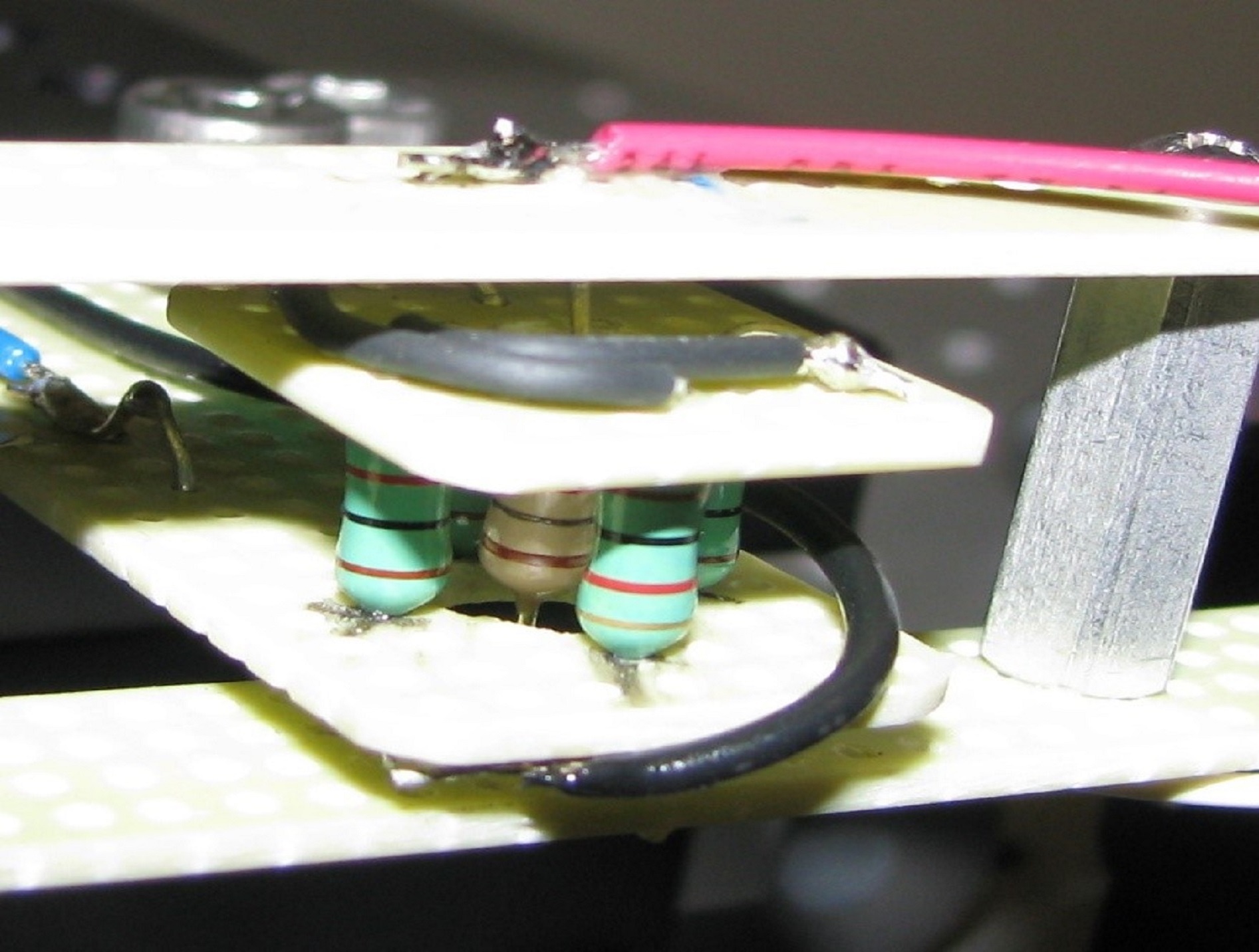
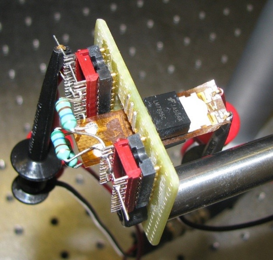
NASA Kennedy Space Center seeks partners interested in the commercial application of the Inductive Non-Contact Position Sensor technology. The Inductive Non-Contact Position Sensor is a highly accurate sensor for motion control applications. The sensor was designed to monitor the precise movements of an optical inspection system that measured defects in Space Shuttle windows. The technology has been prototyped and successfully field-tested with the Shuttle window inspection system. Its small size, low cost, wide range, and accuracy give it a distinct advantage over other types of sensors used for similar applications.
The Technology
Position sensors are used in a range of applications, and there are a number of types tailored to the needs of the applications. Current non-contact inductive sensors are inexpensive but are not precise. Other sensor types, including eddy current sensors, capacitive sensors, and optical/laser position sensors, have high precision, but are larger, more expensive, and require complex algorithms to operate.
Compared to other position sensors, this technology is precise, small, inexpensive, and provides absolute position. It can measure accuracy of position down to 400 nanometers over a total range of 200 microns. The sensor uses inexpensive, off-the-shelf components and has a total volume of less than cubic inch. A highly linear output makes computation easy by using a low-cost microcontroller. The high signal-to-noise ratio allows the sensor to operate in noisy environments.
Although originally designed as a one-dimensional sensor, additional work performed in the laboratory improved the design to make it two-dimensional as well as providing the ability to function as a tip/tilt sensor. The additional work also extended the linear operating region substantially, from about +/- 30 degrees to about +/- 70 degrees. The sensor design can be enlarged to accommodate a larger range of motion; however, enlarging the design may result in a loss of resolution.
Benefits
- High accuracy - Accuracy to 400 nm and resolution of 3 nm/square root hertz
- Small size - Total volume of less than cubic inch
- Low cost - Uses low-cost, off-the-shelf components
- Simple to implement and use - Highly linear measurements may be computed using an inexpensive microcontroller
- Wide operational range - Total operating range of 200 microns
- High signal-to-noise ratio - Can be operated in noisy environments
Applications
- MEMS Accelerometer
- Torsion Rod Measurement
- Vibration Monitoring
- Precision Motion Control -Optical Switches -Hard Drive Control -Semiconductor Lithography -Semiconductor Metrology -Robotic Movement -Medical Diagnostics
Similar Results

Fiber Optic Sensing Technologies
The FOSS technology revolutionizes fiber optic sensing by using its innovative algorithms to calculate a range of useful parameters—any and all of which can be monitored simultaneously and in real time. FOSS also couples these cutting-edge algorithms with a high-speed, low-cost processing platform and interrogator to create a single, robust, stand-alone instrumentation system. The system distributes thousands of sensors in a vast network—much like the human body's nervous system—that provides valuable information.
How It Works
Fiber Bragg grating (FBG) sensors are embedded in an optical fiber at intervals as small as 0.25 inches, which is then attached to or integrated into the structure. An innovative, low-cost, temperature-tuned distributed feedback (DFB) laser with no moving parts interrogates the FBG sensors as they respond to changes in optical wavelength resulting from stress or pressure on the structure, sending the data to a processing system. Unique algorithms correlate optical response to displacement data, calculating the shape and movement of the optical fiber (and, by extension, the structure) in real time, without affecting the structure's intrinsic properties. The system uses these data to calculate additional parameters, displaying parameters such as 2D and 3D shape/position, temperature, liquid level, stiffness, strength, pressure, stress, and operational loads.
Why It Is Better
FOSS monitors strain, stresses, structural instabilities, temperature distributions, and a plethora of other engineering measurements in real time with a single instrumentation system weighing less than 10 pounds. FOSS can also discern between liquid and gas states in a tank or other container, providing accurate measurements at 0.25-inch intervals. Adaptive spatial resolution features enable faster signal processing and precision measurement only when and where it is needed, saving time and resources. As a result, FOSS lends itself well to long-term bandwidth-limited monitoring of structures that experience few variations but could be vulnerable as anomalies occur (e.g., a bridge stressed by strong wind gusts or an earthquake).
As a single example of the value FOSS can provide, consider oil and gas drilling applications. The FOSS technology could be incorporated into specialized drill heads to sense drill direction as well as temperature and pressure. Because FOSS accurately determines the drill shape, users can position the drill head exactly as needed. Temperature and pressure indicate the health of the drill. This type of strain and temperature monitoring could also be applied to sophisticated industrial bore scope usage in drilling and exploration.
For more information about the full portfolio of FOSS technologies, see visit https://technology-afrc.ndc.nasa.gov/featurestory/fiber-optic-sensing

Computer Vision Lends Precision to Robotic Grappling
The goal of this computer vision software is to take the guesswork out of grapple operations aboard the ISS by providing a robotic arm operator with real-time pose estimation of the grapple fixtures relative to the robotic arm’s end effectors. To solve this Perspective-n-Point challenge, the software uses computer vision algorithms to determine alignment solutions between the position of the camera eyepoint with the position of the end effector – as the borescope camera sensors are typically located several centimeters from their respective end effector grasping mechanisms.
The software includes a machine learning component that uses a trained Region-based Convolutional Neural Network (R-CNN) to provide the capability to analyze a live camera feed to determine ISS fixture targets a robotic arm operator can interact with on orbit. This feature is intended to increase the grappling operational range of ISS’s main robotic arm from a previous maximum of 0.5 meters for certain target types, to greater than 1.5 meters, while significantly reducing computation times for grasping operations.
Industrial automation and robotics applications that rely on computer vision solutions may find value in this software’s capabilities. A wide range of emerging terrestrial robotic applications, outside of controlled environments, may also find value in the dynamic object recognition and state determination capabilities of this technology as successfully demonstrated by NASA on-orbit.
This computer vision software is at a technology readiness level (TRL) 6, (system/sub-system model or prototype demonstration in an operational environment.), and the software is now available to license. Please note that NASA does not manufacture products itself for commercial sale.

Pressure Sensor Mechanism
In operation, this RFID-enabled patented technology reacts to a pressure change causing the passive tag to generate an electromagnetic field. The RFID pressure sensor/passive tag reacts to the electromagnetic field and responds by sending a signal to an interrogator. The interrogator receives the reflected signal, measures the returned signal strength indications ("RSSI") of the reflected signal and sends the RSSI measurements and identification of the responding RFID sensors to the processor to determine the pressure. Potential applications for this technology include remote patient mobility monitoring, robotic control systems, and pressure sensing gloves. Older devices may also be outfitted with these sensors to add pressure-monitoring functionality while avoiding the cost of a total system replacement.

RFID Tag System for Precise Asset Tracking & Localization
Commonly used RFID protocols are widely accepted because they are inexpensive and easy to implement. However, the associated low transmit power and narrow bandwidth typically result in coarse local-ization estimates. Often it is desirable to know the precise location of assets without reverting to an entirely different and more expensive protocol. Additionally, many industrial and other applications may desire technology that confirms the mating of components. This new program-mable sensor tag technology facilitates both precise localization and mating confirmation in-part by allowing the RFID sensor tag to become a type of distributed low-cost reader.
To determine a tag attachment, this innovation utilizes a fixed location RFID sensor tag that incorporates a receptacle node to measure an electrical “influence” through resistance, capacitance, inductance, etc. Assets for which localization is desired are outfitted with “influence tags” – devices that produce a set of distinguishable responses when placed in the receptacle region of the RFID sensor tag. Mating or connections are confirmed when electrodes from an influence tag become attached to matching electrodes on a sensor tag’s receptacle node. Information obtained by the RFID sensor tag is stored in its local memory bank through which a dedicated reader can retrieve influence tag information.
Potential applications exist for this technology where specific assets need to be precisely located and/or confirmation is needed when two parts have been correctly connected or attached. This RFID tag technology allows the retrieval of inventory status information in an energy efficient manner from inexpensive, small form factor hardware. Robotic retrieval of assets can be more easily facilitated with this innovation.

Low Cost Star Tracker Software
The current Star Tracker software package is comprised of a Lumenera LW230 monochrome machine-vision camera and a FUJINON HF35SA-1 35mm lens. The star tracker cameras are all connected to and powered by the PC/104 stack via USB 2.0 ports. The software code is written in C++ and is can easily be adapted to other camera and lensing platforms by setting new variables in the software for new focal conditions. In order to identify stars in images, the software contains a star database derived from the 118,218-star Hipparcos catalog [1]. The database contains a list of every star pair within the camera field of view and the angular distance between those pairs. It also contains the inertial position information for each individual star directly from the Hipparcos catalog. In order to keep the star database size small, only stars of magnitude 6.5 or brighter were included. The star tracking process begins when image data is retrieved by the software from the data buffers in the camera. The image is translated into a binary image via a threshold brightness value so that on (bright) pixels are represented by 1s and off (dark) pixels are represented by 0s. The binary image is then searched for blobs, which are just connected groups of on pixels. These blobs represent unidentified stars or other objects such as planets, deep sky objects, other satellites, or noise. The centroids of the blob locations are computed, and a unique pattern recognition algorithm is applied to identify which, if any, stars are represented. During this process, false stars are effectively removed and only repeatedly and uniquely identifiable stars are stored. After stars are identified, another algorithm is applied on their position information to determine the attitude of the satellite. The attitude is computed as a set of Euler angles: right ascension (RA), declination (Dec), and roll. The first two Euler angles are computed by using a linear system that is derived from vector algebra and the information of two identified stars in the image. The roll angle is computed using an iterative method that relies on the information of a single star and the first two Euler angles.
[1] ESA, 1997, The Hipparcos and Tycho Catalogues, ESA SP-1200



