Beam Crossing Optical System
Optics
Beam Crossing Optical System (LAR-TOPS-346)
Novel system enabling 2-point Focused Laser Differential Interferometry
Overview
NASA's Langley Research Center has developed a Beam Crossing Optical System for use in two-point Focused Laser Differential Interferometers (FLDI) that are used in measuring density disturbances in hypersonic flows. Conventional single point FLDI systems only measure how flow fluctuates. In contrast, with the two-point system, velocity can be measured between the two points to compute spatial changes and measure fluctuating flow. In this design, laser beams propagating between the transmitter and receiver sides of the FLDI instrument remain parallel to one another so that velocity bias errors that occur in the conventional testing region with angled beams are eliminated, increasing accuracy and decreasing uncertainty of sensitivity measurements. The technology offers a lower-cost (half the cost) alternative to a Nomarski Prism approach and enables increased manipulation capabilities for the user, such that the separation distance between points and laser beam orientation can be manually adjusted with ease.
The Technology
The conventional approaches for measuring focused laser differential interferometry either use a single-point mechanism that cannot calculate velocity or a system that creates non-parallel beams in the testing zone, causing differences in time to travel between beams throughout the testing zone, adding a level of uncertainty to velocity measurements.
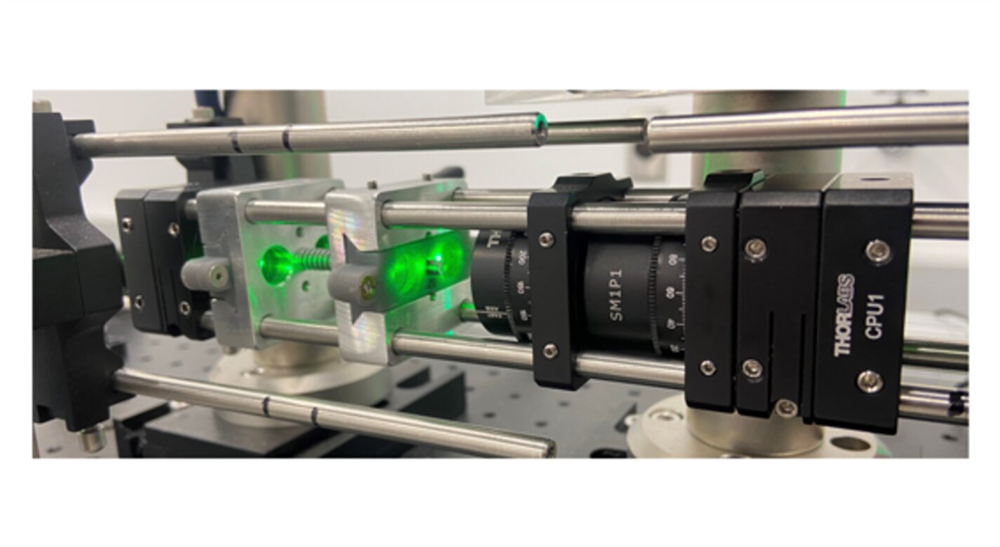
For this technology, the inventors determined that the best approach is to use a method that ensures all laser beams propagating between the transmitter and receiver sides of the instrument are parallel to one another. This is done by crossing two orthogonally polarized beams at a Wollaston prism located just ahead of the field lens on the transmitter side of the FLDI. The polarization orientation of the two crossing beams must be at ±45 degrees to one another so that the Wollaston prism can further split the beams by a small angle (this gives the instrument its sensitivity to density fluctuations at each measurement point).
The use of wedge prisms (that comprise the beam crossing system) to redirect the split beams such that they cross the optical axis minimizes any distortion imparted to the beams. This is in contrast to the use of a spherical focusing lens to redirect the split beams, which can impart undesirable distortions to the beams and affect the focusing properties of the FLDI instrument between its transmitter and receiver sides.


Benefits
- Enables simultaneous two-point measurement capability: Easily incorporated into a conventional single-point FLDI instrument to offer two-point measurements
- Eliminates velocity bias errors: Ensures the laser beams propagating between the transmitter and receiver sides of the FLDI instrument remain parallel to one another
- Permits tunable adjustments: The laser beams remain symmetric about the FLDI instrument’s optical axis, enabling the user to quickly adjust the orientation of the laser beams by simple rotation of the proposed optical system technology
- Provides a more cost-effective approach to FLDI: The hardware of the new NASA system costs 50% of Nomarski Prism
- Promotes user manipulation of separation distance: Design allows for easy-to-make changes to precisely align the crossing point of the beams
- Polarizing prism flexibility: The relative rotation of the wedged prism pairs allows the system to operate as a variety of adjustable polarizing prisms (e.g., Nomarski, Wollaston, Rochon, beam displacer, etc.)
Applications
- Medical Research: Differential Interference Contrast (DIC) Microscopy for cell investigation
- Gas Leak Monitoring: Use in Laser-Induced Thermal Acoustics (LITA) for gas sensing
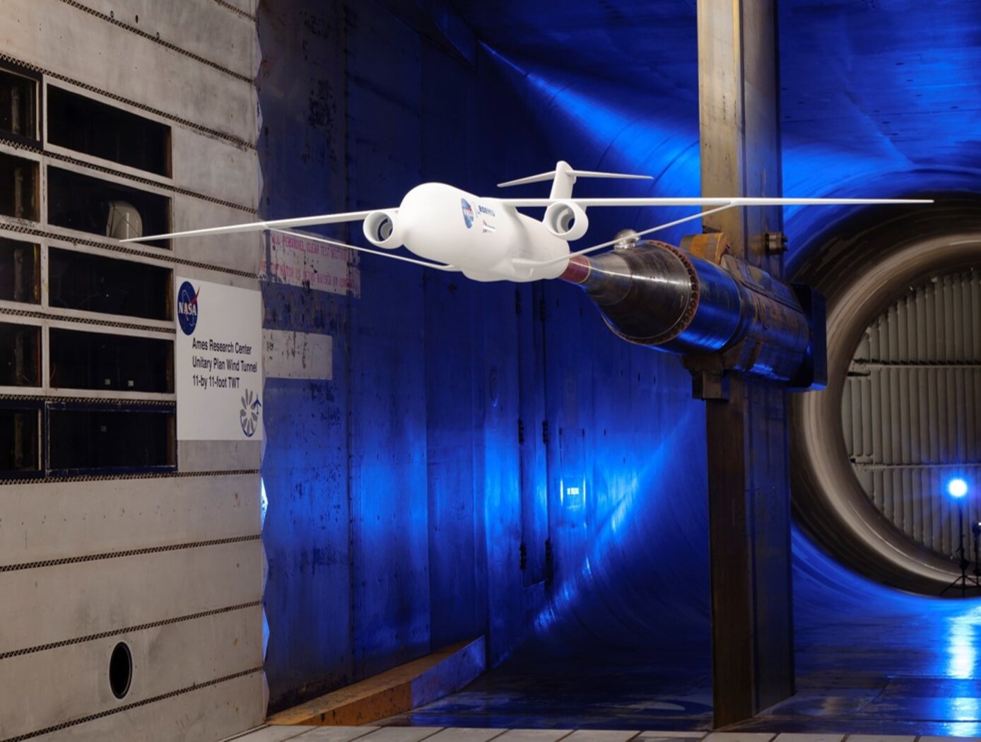
- Aerospace and Aviation: Supersonic wind tunnel testing for various applications in aircraft development
- Academic Research: Fundamental physics research of Focused Laser Differential Interferometry (FLDI)
- Global Doppler: Two-component Doppler velocimetry with planar laser-induced-fluorescence (PLIF) for measurements in wavelength shifts
|
Tags:
|
Similar Results

Optical Mass Sensor for Multi-Phase Flows
Unlike commercial turbine and Venturi-type sensors, which are flow intrusive and prone to high error rates, NASA's new flow sensor technology uses an optical technique to precisely measure the physical characteristics of a liquid flowing within a pipe. It generates a reading of the flows density, which provides a highly accurate mass flow measurement when combined with flow velocity data from a second optical sensor.
NASA's sensor technology provides both a void fraction measurement, which is a measurement of the instantaneous gas/liquid percentage of a static volume and a quality measurement, which is the fraction of flow that is vapor as part of a total mass flow. It also provides a direct measurement of the gas/liquid concentration within the flow, making it suited for real-time measurement of multi-phase flows.
The technology was originally developed to accurately determine the flow rates and tank levels of multi-phase cryogenic fuels used on various NASA vehicles including the Space Shuttle and in ground-based propulsion testing. It can also be used for a wide range of gas/liquid ratios, flows with complex cross sectional profiles, flows containing bubbles or quasi-solids, and essentially any liquid, gas, or multi-phase flow that can be optically characterized. Because it is insensitive to position, the new technology also has potential for use in zero-gravity tank level sensors.

Active Pointing and Tracking System in Laser Satellite to Satellite Tracking (SST)
The Active Pointing and Tracking System in Laser Satellite to Satellite Tracking utilizes a design to correct yaw and pitch range error. An aircraft in flight is free to rotate in three dimensions: yaw (nose left or right about an axis running up and down), pitch (nose up or down about an axis running from wing to wing), and roll (rotation about an axis running from nose to tail). The axes are alternatively designated as vertical, transverse, and longitudinal respectively. These axes move with the vehicle and rotate relative to the Earth along with the craft. In current systems, path length will change with satellite yaw and pitch.
The Active Pointing and Tracking System utilizes a fast mirror places at the center of mass of the satellite, with the detector is a distance away from the mirror. With yaw and pitch movement of the satellite, the center of mass has no added displacement, and the detector to the mirror distance does not change. The yaw and pitch angle change are compensated with the mirror angle turning. There is no path length change with the optical configuration.

Space Optical Communications Using Laser Beams
This invention provides a new method for optical data transmissions from satellites using laser arrays for laser beam pointing. The system is simple, static, compact, and provides accurate pointing, acquisition, and tracking (PAT). It combines a lens system and a vertical-cavity surface-emitting laser VCSEL)/Photodetector Array, both mature technologies, in a novel way for PAT. It can improve the PAT system's size, weight, and power (SWaP) in comparison to current systems. Preliminary analysis indicates that this system is applicable to transmissions between satellites in low-Earth orbit (LEO) and ground terminals. Computer simulations using this design have been made for the application of this innovation to a CubeSat in LEO. The computer simulations included modeling the laser source and diffraction effects due to wave optics. The pointing used a diffraction limited lens system and a VCSEL array. These capabilities make it possible to model laser beam propagation over long space communication distances. Laser beam pointing is very challenging for LEO, including science missions. Current architectures use dynamical systems, (i.e., moving parts, e.g., fast-steering mirrors (FSM), and/or gimbals) to turn the laser to point to the ground terminal, and some use vibration isolation platforms as well. This static system has the potential to replace the current dynamic systems and vibration isolation platforms, dependent on studies for the particular application. For these electro-optical systems, reaction times to pointing changes and vibrations are on the nanosecond time scale, much faster than those for mechanical systems. For LEO terminals, slew rates are not a concern with this new system.

Fine-pointing Optical Communication System Using Laser Arrays
A new method is described for optical data transmissions from satellites using laser arrays for fine pointing of laser beams that use body pointing. It combines a small lens system and a VCSEL/Photodetector Array in a novel way to provide a fine pointing capability for laser beams that are pointed by body pointing of a CubeSat. As Fig. 1 shows, an incoming laser beam (green or blue, with rightward arrows), transmitted from a ground terminal, enters the lens system, which directs it to an element of the pixel array (gray rectangle). Each element, or pixel, consists of a VCSEL component/photodetector pair. The photodetector detects the incoming beam, and the VCSEL component returns a modulated beam to the lens system (green or blue, with leftward arrows), which sends it to the ground terminal. As the incoming beam changes direction, e.g., from the blue to the green incoming direction, this change is detected by the adjacent photodetector, and the laser paired with that photodetector is turned on to keep the outgoing laser beam on target. The laser beams overlap so that the returning beam continues to point at the ground terminal. The VCSEL component may consist of a single VCSEL or a cluster of VCSELs. Figure 2 shows the propagation of two overlapping laser beams. The system can very accurately point finely focused diffraction-limited laser beams. Also, simultaneous optical multiple access (OMA) is possible from different transceivers within the area covered by the laser array. For this electro-optical system, reaction times to pointing changes and vibrations are on the nanosecond time scale, much faster than mechanical fine pointing systems.

Reconfigurable Local Oscillator for Coherent Optical Detection
The innovation expands the range of signals that coherent optical receivers can detect. Unlike traditional systems with fixed LOs, this approach allows real-time adjustments to an LO’s properties, such as frequency, phase, polarization, amplitude, spatial mode, or timing, to better match incoming signals. These adjustments improve measurement accuracy and signal recovery in various scenarios, such as shifting heterodyne frequencies into the receiver’s bandwidth or adapting to different signal polarizations. The innovation lies in the ability to switch an LO's configurations on the fly using technologies like fiber-optic or integrated photonic switches, as well as other methods like optical modulation or tunable delay lines. This dynamic capability allows coherent receivers to switch seamlessly between range-Doppler and Doppler-only modes. As a result, a single system can track both nearby, slow-moving targets and distant, high-velocity objects (up to 20+ km/s) while operating with a compact, low-speed receiver (


