Annular Ion Engine
propulsion
Annular Ion Engine (LEW-TOPS-74)
Enables high thrust density for electric propulsion systems
Overview
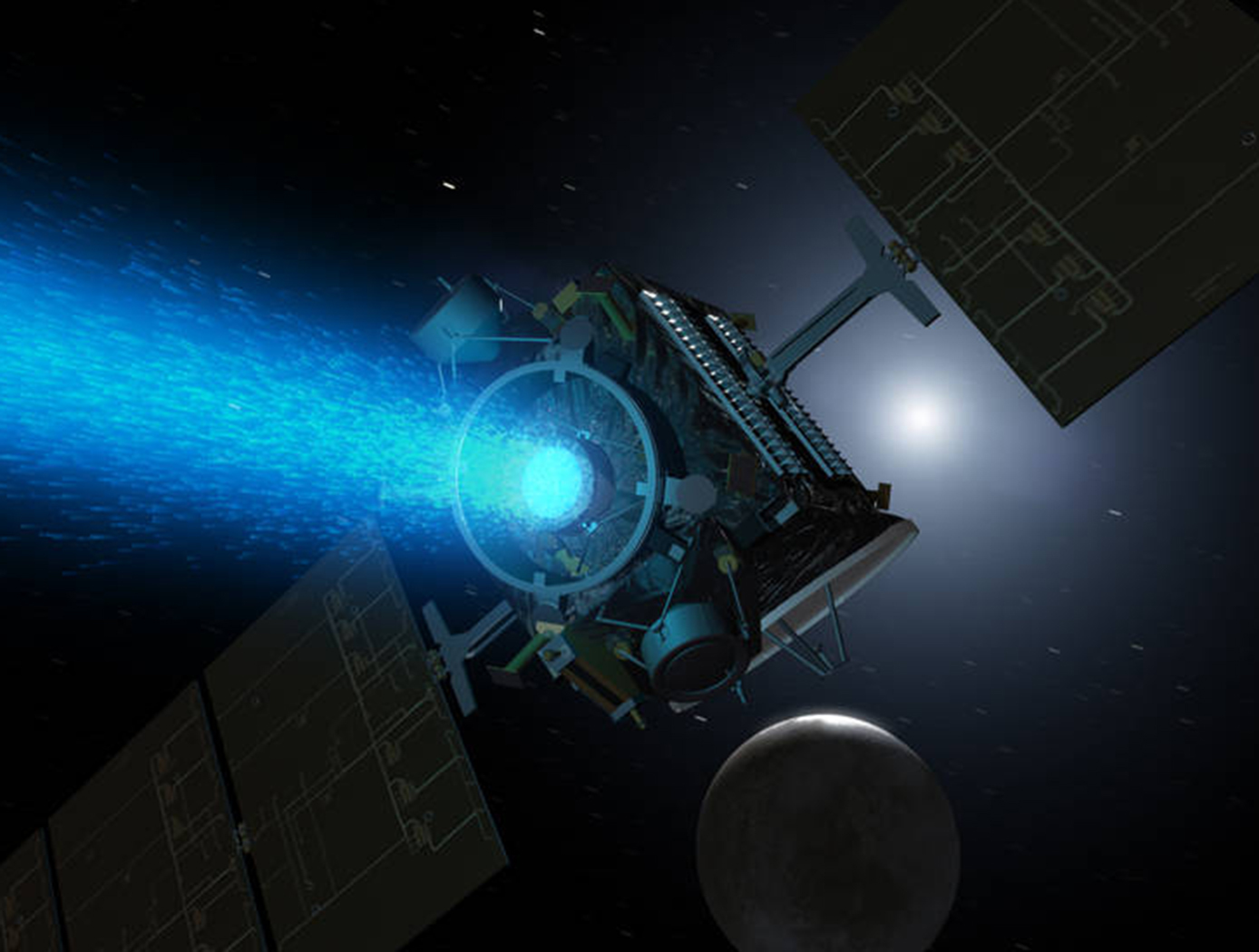
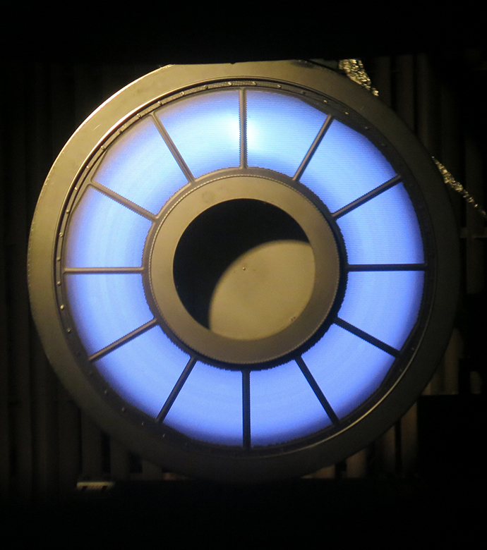
Innovators at NASA's Glenn Research Center have developed a breakthrough in ion thruster technology. The Annular Ion Engine (AIE) features an annular discharge chamber with a set of annular ion optics, potentially configured with a centrally mounted neutralizer cathode assembly. Compared to current state-of-the-art, cylindrically shaped ion thrusters, the AIE includes two primary advantages: 1) it enables scaling of ion thruster technology to high power at specific impulse (Isp) desirable for near-term missions, and 2) it provides a substantial increase in both thrust density and thrust-to-power (F/P) ratio. With its additional increase in lifetime service and improvements in packaging, Glenn's AIE represents the next generation of electric propulsion systems that require higher power, F/P, and efficiency, such as Solar Electric Propulsion (SEP) vehicles that may transport humans to the moon and Mars.
The Technology
The advantages displayed by Glenn's AIE stem from a number of novel design concepts, centered on an annular discharge chamber with a set of annular ion optics. The annular discharge chamber increases the effective anode surface area for electron collection as compared to a conventional cylindrically shaped ion thruster of equivalent beam area. With this increased surface area, the AIE can operate at higher discharge currents and therefore high beam currents, thereby yielding a significantly increased (3x) thrust density. An annular-geometry flat electrode can be added to enable higher-perveance designs with even higher thrust densities, with improved F/P and efficiencies compared to more conventional, spherically domed electrodes. In addition, Glenn's design allows the neutralizer cathode assembly (NCA) to be placed in a central position within the annulus, which not only eliminates the cantilevered-outboard NCA used in most conventional ion thrusters but also enables a shared gimbal platform. These benefits make manufacturing the AIE simpler as well as allowing more compact engine designs. All of these advantages add up to an electric propulsion machine that yields superior performance over the entire Isp range, making the AIE attractive for next-generation SEP vehicles. Glenn's technological advance enables spacecraft to travel farther, faster, and more cheaply than with any other propulsion technology - with clear benefits for NASA and commercial space applications.


Benefits
- High power: Relatively small electron spans deliver as much as 10x the power capability
- High performance: Up to 3x increase in thrust density over conventional cylindrically shaped ion thruster
- Efficient: Realizes frugal propellant usage and very high exhaust velocity
- Durable: Comparatively simple design results in 10x increase in lifetime
- Scalable: Electric propulsion systems from 10kW to 300kW and higher
Applications
- Aerospace
- Commercial space
- Military
- Propulsion (e.g., SEP vehicles, station keeping, deep space probes)
- Satellites
Similar Results

Anode Manifold Plug for Hall Effect Thrusters
Flow-restricting features in a Hall thruster anode manifold assembly, typically precision manufactured orifices, can contribute to significant flow non-uniformity if tolerances on the features are not properly controlled. Non-uniformity in flow distribution negatively impacts thruster performance. The anode assembly is usually a complex and expensive assembly to manufacture. Removing the flow restricting elements from the anode manifold structure in favor of modular insertable subcomponents (i.e., plugs) enables the use of more reliable and repeatable precision manufacturing techniques. The resulting components can be tested, characterized, and sorted for acceptance before being installed into the larger anode assembly (i.e., quality control can be performed at the subcomponent level). This may lead to increased performance and yield rate of the final assembly.
The flow restrictor plugs can be made in many different ways. The most basic flow restrictor takes the form of a precision hole machined into a cylinder, where the cylinder is then press fit into a hole drilled into the anode base. Alternate embodiments of the flow restrictor include precision machined nozzles, laminar flow elements, or sintered porous metal elements. The flow restrictor can also be made from a different material than the anode base, such as a precision ruby orifice contained in a metal carrier which is installed in a metal anode base. The plugs can be installed in a variety of ways, all of which create hermetic seals. Installation can include a press fit relying on plastic deformation or threading the plug component into the anode base. Welding on the top surface of the anode base can also be done to provide a robust hermetic seal.

High Propellant Throughput Small Spacecraft Electric Propulsion Thruster
NASAs High Propellant Throughput Small Spacecraft Electric Propulsion thruster offers a propellant throughput capability of greater than 120 kg with a nominal thruster efficiency greater than 50%. The new thruster design combines heritage Hall thruster component design approaches with recent NASA GRC advancements in the areas of advanced magnetic circuit design, robust propellant manifolds, and center mounted cathodes. Prototypes of the High Propellant Throughput Small Spacecraft Electric Propulsion thruster have been fabricated and proof-of-concept has been demonstrated.
A significant advancement in the High Propellant Throughput Small Spacecraft Electric Propulsion thruster is NASA's optimized magnetically shielded (OMS) field topology. The new OMS configuration reduces discharge channel erosion rates compared to conventional Hall thrusters, while reducing front pole cover erosion rates compared to traditional magnetically shielded Hall thrusters. This system also includes a largely unibody structure to reduce fabrication cost, increase strength, and optimize thermal management. A coupling plate between the high voltage discharge channel and low voltage thruster body allows more efficient thruster assembly and verification processes. Other design advancements further simplify assembly, improve robustness, and optimize performance.

Hall Effect Thruster Technologies
Used for propelling Earth-orbiting satellites and deep-space robotic vehicles, the HET gets its name because it traps electrons with an intense radial magnetic field in an azimuthal Hall current moving around the circumference of an annular ceramic channel. The electrons in the circulating Hall current ionize the onboard propellant - the inert gas xenon - and create an ionized plasma. The xenon plasma is then accelerated axially, via an applied electric field along the coaxial channel, to an exit velocity of up to 65,000 miles per hour to produce thrust. The interaction of the accelerated plasma and the downstream edge of the channel, where the plasma is the most energetic, results in erosion of the surrounding magnetic system used to generate the plasma. One of NASA Glenn's novel designs relies on an azimuthally symmetric configuration that minimizes radial magnetic fields at the discharge chamber walls. This configuration completely shields the walls of the discharge chamber from the high-energy plasma ions. With regard to the discharge-channel-wall replacement innovation, an actuator can be configured to extend the discharge chamber along the centerline axis. The actuator can be either mechanical or programmable. In either case, the sleeve can be extended while an upstream portion of the discharge chamber remains stationary, thereby preventing plasma exposure. These novel designs increase the efficiency and extend the lifetime of the HET to five times that of unshielded thrusters, enabling a new era of space missions.

Small Spacecraft Electric Propulsion (SSEP) Technology Suite
Innovators at GRC have developed a suite of SSEP technologies for small, low-power spacecraft using Hall effect thrusters including a high propellant throughput small spacecraft electric propulsion thruster (LEW-TOPS-158), a power processing unit for SSEP (LEW-TOPS-157), an anode manifold plug for Hall effect thrusters (LEW-TOPS-159), and additional Hall effect technologies (LEW-TOPS-34). See the Additional Information section at the bottom of the page for more information on each technology suite component.
GRC is making these technologies available to U.S. companies through a no-cost*, non-exclusive license agreement and companion Space Act Agreement. Licensees may receive a comprehensive package of design and process documents including issued and pending patents, design drawings, materials specifications, and test data. Licensees will assist in defining system requirements and creating new platforms to use the SSEP technologies. This streamlined, collaborative commercialization strategy helps satisfy NASA exploration and science mission requirements while improving U.S. competitiveness in the global electric propulsion market and improving the success of new electric propulsion developments. Working alongside our licensees, GRC hopes to generate a compendium of SSEP knowledge as a living document, maintained by all users in a consortia-like environment.
*Although the license and Space Act Agreement are no cost to the licensees, licensees would be responsible for setting up and maintaining an EAR restricted file sharing space.

Improved Hypersonic Aircraft Flight Control System
NASA’s MHD patch technology is composed of two electrodes positioned a prescribed distance apart recessed into angled channels on the surface of the TPS of an aircraft or spacecraft and an electromagnetic coil placed directly below the electrodes with the magnetic field protruding out of the surface. Note that the recessed/angled MHD patch described here is a special version of the original MHD patch described in LAR-TOPS-363. During hypersonic flight, the conductive ionizing atmospheric flow over the surface permits current to flow between the two electrodes. This current is harnessed to power the electromagnet which in turn generates strong Lorentz forces that augment lift and drag forces for guidance, navigation, and control of the craft. Alternatively, the current can be used to charge a battery. Changing the size of the MHD patch (e.g., the length or distance between the electrodes), the strength of the electromagnet, or the direction of the magnetic field enables tuning of generated forces for a given craft design. Multiple MHD patches can be leveraged on a single craft.
In-silico evaluation of the non-recessed, non-angled MHD patch technology on select aeroshell designs for mock entry into planetary atmospheres has been performed. A single 1m2 MHD patch exerts forces up to 200 kN under simulated Neptune atmosphere entry that can be used to control a craft.


