Spacecraft to Remove Orbital Debris
Aerospace
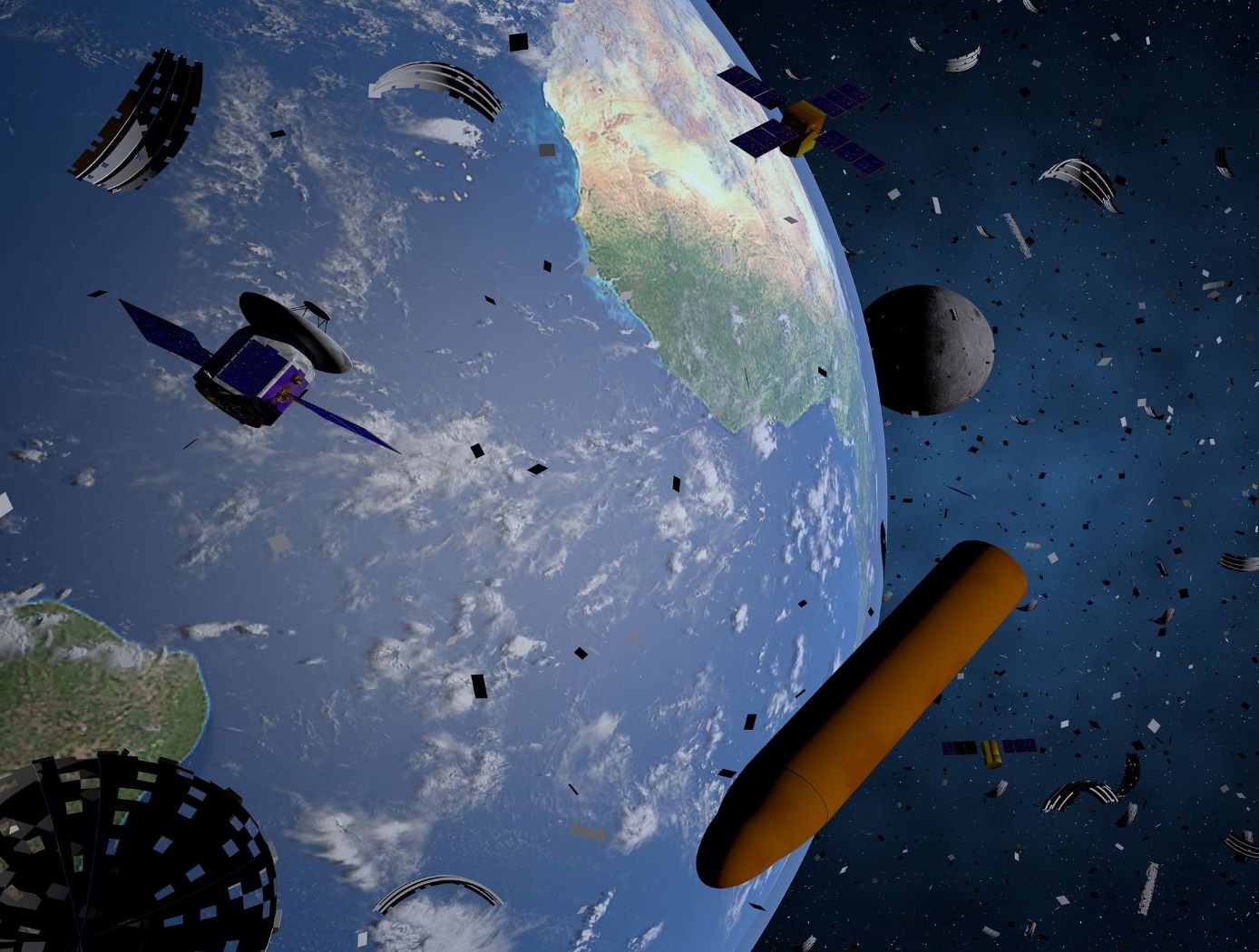
Spacecraft to Remove Orbital Debris (MSC-TOPS-90)
Concept to allow autonomous capture of debris in LEO
Overview
Innovators at NASA Johnson Space Center have designed an Active Debris Removal Vehicle (ADRV) that can remove large orbital debris from low-Earth orbit (LEO). The ADRV will approach a debris object, assess its characteristics and motion, determine an initial capture trajectory, match its rotation rates, execute a capture maneuver, and control and deorbit the object. This concept can help mitigate catastrophic collisions with debris involving astronauts, their spacecraft, and other valuable space assets. The ADRV incorporates several NASA inventions including a novel spacecraft control system, debris object characterization system, and capture and release system. These NASA ADRV technologies may also be applied to satellite servicing and orbital adjustments.
The Active Debris Removal Vehicle (ADRV) is at technology readiness level (TRL) 6 (which means the system/sub-system model or prototype has been demonstrated in an operational environment) and the related issued patent is now available to license. Please note that NASA does not manufacture products itself for commercial sale.
The Technology
An approach to mitigating the creation of additional orbital debris is to remove the sources of future medium debris by actively removing large spent objects from congested orbits. NASA has introduced the ADRV, an efficient and effective solution to remove large debris from LEO such as spent rocket bodies and non-functional satellites. The concept yields a single use, low-cost, lightweight, high mass fraction vehicle that enables the specific removal of large orbital debris (1000 - 4000 kg mass, 200 - 2000 km altitude, and 20 – 98-degree inclination). The ADRV performs rendezvous, approach, and capture of non-cooperative tumbling debris objects, maneuvering of the mated vehicle, and controlled, targeted reposition or deorbit of the mated vehicle. Due to its small form factor, up to eight ADRVs can be launched in a single payload, enabling high impact orbital debris removal missions within the same inclination group.
Three key technologies were developed to enable the ADRV: - 1) The spacecraft control system (SCS) is a guidance, navigation, and control system that provides vehicle control during all phases of a mission; - (2) The debris object characterization system (DOCS) characterizes movement and capture of non-cooperative targets; and - (3) The capture and release system (CARS) allows the vehicle to capture and mate with orbital debris targets. These technologies can improve the current state-of-the-art capabilities of automated rendezvous and docking technology significantly for debris objects with tumbling rates up to 25 degrees per second. This approach leverages decades of spaceflight experience while automating key mission areas to reduce cost and improve the likelihood of success.

Benefits
- Protects space and ground assets from debris exposure risk
- Small form factor enables reduced launch costs
- Eight ADRVs can be launched on a single payload allowing multiple missions
- Bi-propellant hypergolic propulsion system can achieve high mass fractions for efficient maneuver and removal operations
- The capture and release system (CARS) snare design can adaptively capture a variety of uncooperative targets not designed for capture
- Developed to be a low-cost alternative to other proposed orbital debris removal systems
Applications
- Orbital debris removal
- Satellite orbiting adjustments, servicing, deorbiting
|
Tags:
|
Similar Results

Space Traffic Management (STM) Architecture
As ever larger numbers of spacecraft seek to make use of Earth's limited orbital volume in increasingly dense orbital regimes, greater coordination becomes necessary to ensure these spacecraft are able to operate safely while avoiding physical collisions, radio-frequency interference, and other hazards. While efforts to date have focused on improving Space Situational Awareness (SSA) and enabling operator to operator coordination, there is growing recognition that a broader system for Space Traffic Management (STM) is necessary. The STM architecture forms the framework for an STM ecosystem, which enables the addition of third parties that can identify and fill niches by providing new, useful services. By making the STM functions available as services, the architecture reduces the amount of expertise that must be available internally within a particular organization, thereby reducing the barriers to operating in space and providing participants with the information necessary to behave responsibly. Operational support for collision avoidance, separation, etc., is managed through a decentralized architecture, rather than via a single centralized government-administered system.
The STM system is based on the use of standardized Application Programming Interfaces (API) to allow easier interconnection and conceptual definition of roles to more easily allow suppliers with different capabilities to add value to the ecosystem. The architecture handles basic functions including registration, discovery, authentication of participants, and auditable tracking of data provenance and integrity. The technology is able to integrate data from multiple sources.
MMOD Impact Detection and Location
Multiple strain sensors encoded into one or more optical fibers are affixed to a MMOD shield or structure. The optical fiber(s) is/are connected to a data collection device that records strain data at a frequency sufficient to resolve MMOD impact events. Strain data are processed and presented on a computer display. MMOD impact imparts a transient shock loading to a structure which is manifested as transient strain as the shock wave moves through the structure. MMOD impacts are determined from the time signature of, both, measured strain from multiple sensors on the optical fiber(s) as well as strain resulting from plastic strain induced in the MMOD shield and structure as a consequence of the MMOD impact (for materials exhibiting plastic strain). The array of strain sensors, encoded into one or more optical fibers using Fiber Bragg Grating (FBG) technology, records time varying strain to identify that a strike has occurred and at what time it occurred. Strike location information can be inferred from the residual plastic strain recorded by the multitude of strain sensors in the fiber(s). One or more optical fibers may be used to provide optimal coverage of the area of interest and/or to ensure a sufficient number of strain measurements are provided to accurately characterize the nature of the impact.

Computer Vision Lends Precision to Robotic Grappling
The goal of this computer vision software is to take the guesswork out of grapple operations aboard the ISS by providing a robotic arm operator with real-time pose estimation of the grapple fixtures relative to the robotic arm’s end effectors. To solve this Perspective-n-Point challenge, the software uses computer vision algorithms to determine alignment solutions between the position of the camera eyepoint with the position of the end effector – as the borescope camera sensors are typically located several centimeters from their respective end effector grasping mechanisms.
The software includes a machine learning component that uses a trained Region-based Convolutional Neural Network (R-CNN) to provide the capability to analyze a live camera feed to determine ISS fixture targets a robotic arm operator can interact with on orbit. This feature is intended to increase the grappling operational range of ISS’s main robotic arm from a previous maximum of 0.5 meters for certain target types, to greater than 1.5 meters, while significantly reducing computation times for grasping operations.
Industrial automation and robotics applications that rely on computer vision solutions may find value in this software’s capabilities. A wide range of emerging terrestrial robotic applications, outside of controlled environments, may also find value in the dynamic object recognition and state determination capabilities of this technology as successfully demonstrated by NASA on-orbit.
This computer vision software is at a technology readiness level (TRL) 6, (system/sub-system model or prototype demonstration in an operational environment.), and the software is now available to license. Please note that NASA does not manufacture products itself for commercial sale.

Multi-Stage Filtration System
While HEPA filter elements can last for years without intervention, pre-filtering systems that remove larger particles before they reach the HEPA filter need to be treated (most often by cleaning or replacement) as often as once a week. These treatments can be resource-intensive and expensive, especially in extreme environments. Glenn's innovative system combines a pre-filtration impactor and a scroll filter that reduces the need to replace the more sensitive or expensive filters, extending the system's working life. The system uses an endless belt system to provide the impaction surface. A thin layer of low-toxicity grease is applied to the impaction surface to increase particle adhesion. A high flow turning angle near the impaction surface causes relatively large particles to impact and stick to the surface while smaller particles stay within the air flow. When the surface is covered with particles - or if a layer of particles has grown to a thickness that impairs adhesion - the surface is regenerated. The band is rotated so that the loaded surface passes by a scrapper, removing the layer of particles and a clean segment of the band revolves to become the new impaction surface.
A further innovation is the scroll filter which allows the filtration media to be rotated out of the airflow when fully loaded, providing multiple changes of the filter through a motorized scrolling or indexing mechanism. When nearly fully loaded with dust particles, the exposed media is mechanically rolled up on one side of the filter to both contain and compactly store the dust. The spools that hold the clean and spent filter media are mounted on roller bearings to facilitate the scrolling operation and reduce motor power requirements. Nearly any grade of filter media can be used to meet the desired filtration specification. Additional media rolls can be added after the original roll is spent to further increase filter life.

Visual Inspection Posable Invertebrate Robot (VIPIR)
Initially developed as a close quarters inspection tool capable of accessing hard to reach, tight, or visibly restricted, areas of satellites, the VIPIR system can be used to remotely inspect inaccessible locations such as behind a sheet of thermal blanketing material, into a satellites plumbing, or perhaps even deep inside the otherwise unreachable crevasses of a spacecraft bus. The VIPIR system incorporates a number of subassemblies for incredible operational freedom and capabilities for imaging and dissemination of componentry.
VIPIR’s Video Borescope Assembly (VBA) is a flexible snake-camera capable of multidirectional articulations, making steering and control simple and intuitive for an operator. The VBA also includes at least one imaging sensor and lighting to see in dark, confined spaces. Real-time, high-resolution visual information can be fed back to an operator for live analysis. A reel system extends and retracts the VBA with the use of a spool, and includes position indicators for deployment tracking. The Tendon Management System (TMS), not unlike human tendons, utilizes pulleys and tensioners to articulate the VBA in the confined spaces. A seal system ensures the VBA is free of contamination.
VIPIR underwent space-based testing on the ISS during the Robotic Refueling Phase 2 (RRM-2) mission designed to showcase and test several NASA advanced robotic satellite servicing technologies. During this mission, VIPIR demonstrated state-of-the-art near and midrange inspection capabilities. NASA’s VIPIR system is available for licensing to industry, and may be desirable to companies focused on satellite servicing, on-orbit assembly, and other applications requiring detailed inspection of assets in space.

