Vertiport Assessment and Mobility Operations System (VAMOS!)
aerospace
Vertiport Assessment and Mobility Operations System (VAMOS!) (TOP2-298)
Advanced Air Mobility (AAM) Infrastructure Planning System
Overview
It is widely believed that Advanced Air Mobility (AAM) is poised to have a significant societal impact in the coming years to move people and cargo more rapidly and efficiently. The main goals of AAM vehicles are to reduce emissions, to increase connectivity and speed, while helping to reduce traffic congestion. These vehicles can take off and land vertically in designated urban locations called vertiports. The widespread adoption of AAM concept will necessitate vertiports to be located throughout a geographical region. There is a need to systematically evaluate and quantify which locations are better suited for vertiports and how these vertiports will work together in a network. NASA Ames Research Center has designed a novel technology called VAMOS! that evaluates a variety of factors, e.g., intermodal centers, environmental impact, zoning/land use, to determine the most suitable locations for vertiports in a desired city/region.
The Technology
The term Advanced Air Mobility (AAM) refers to a new mode of transportation utilizing highly automated airborne vehicles for transporting goods and/or people. The adoption of widespread use of AAM vehicles will necessitate a network of vertiports located throughout a geographical region. A vertiport refers to a physical structure for the departure, arrival, and parking/storage of AAM vehicles. NASA-developed Vertiport Assessment and Mobility Operations System (VAMOS!) enables identifying geographical locations suitable for locating a vertiport or assessing suitability of pre-selected locations. For example, suitability evaluation factors include zoning, land use, transit stations, fire stations, noise, and time-varying factors like congestion and demand.
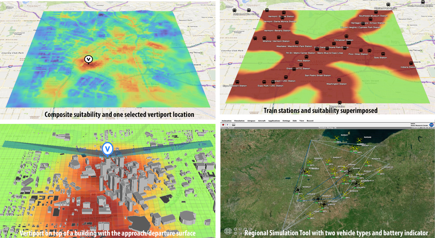
The vertiport assessment system assigns suitability values to these factors based on user-input, and types, including location-based (e.g., proximity to mass transit stations), level-based (e.g., noise levels), characteristic-based (e.g., residential zoning), and time-based (e.g., demand). Based on user input, the system spreads a grid over the geographical area, specifies importance criteria and weights for scaling the impact of the suitability factors, and identifies specific sub-regions as candidate locations. The candidate sub-regions are shown on a user interface map overlay in a color-coded gradient that reflects the suitability strength for a sub-region. Vertiport locations are selected within these sub-regions. These candidate vertiport locations are refined by establishing feasibility of flight between them. VAMOS! includes a modeling component and a simulation component. The modeling component assists a user to identify one or more geographical locations at which a vertiport may be physically built. The simulation component of the technology displays, in real-time, the simulated operational behavior of AAM vehicles and in the context of their projected flight paths combined with data dynamically obtained from live sources. These data sources can be from the Federal Aviation Administration (FAA) or other private or public governing bodies, from one or more AAM vehicles in flight, and from weather sources.

Benefits
- Vertiports are a necessary part of Advanced Air Mobility as an emerging industry
- The technology enables customization of assessment factors for the local cities and communities
- Delivers a simple and optimized interface for city planners and communities to use
- Provides graphical location suggestions for vertiport selection, risk assessment, economic analysis, etc.
- Allows frequency and density impact assessment
- Offers flight route structure design (for avoidance of weather, noise, risk management, etc.)
- Open architecture
Applications
- Advanced Air Mobility (AAM) industry
- City planners/Departments of Transportation
- Vertiport developers
- Electric Vertical Take Off and Landing (eVTOL) vehicle manufacturers and designers
- Research institutions for research on:     Noise modeling     Surface mobility data     Ground congestion information     Vehicle flight route structure     Battery health assessment
Technology Details
aerospace
TOP2-298
ARC-18591-1
Patent Pending
|
Tags:
|
Similar Results

Vision-based Approach and Landing System (VALS)
The novel Vision-based Approach and Landing System (VALS) provides Advanced Air Mobility (AAM) aircraft with an Alternative Position, Navigation, and Timing (APNT) solution for approach and landing without relying on GPS. VALS operates on multiple images obtained by the aircraft’s video camera as the aircraft performs its descent. In this system, a feature detection technique such as Hough circles and Harris corner detection is used to detect which portions of the image may have landmark features. These image areas are compared with a stored list of known landmarks to determine which features correspond to the known landmarks. The world coordinates of the best matched image landmarks are inputted into a Coplanar Pose from Orthography and Scaling with Iterations (COPOSIT) module to estimate the camera position relative to the landmark points, which yields an estimate of the position and orientation of the aircraft. The estimated aircraft position and orientation are fed into an extended Kalman filter to further refine the estimation of aircraft position, velocity, and orientation. Thus, the aircraft’s position, velocity, and orientation are determined without the use of GPS data or signals. Future work includes feeding the vision-based navigation data into the aircraft’s flight control system to facilitate aircraft landing.

Near-Real Time Verification and Validation of Autonomous Flight Operations
NASA's Extensible Traffic Management (xTM) system allows for distributed management of the airspace where disparate entities collaborate to maintain a safe and accessible environment. This digital ecosystem relies on a common data generation and transfer framework enabled by well-defined data collection requirements, algorithms, protocols, and Application Programming Interfaces (APIs). The key components in this new paradigm are:
Data Standardization: Defines the list of data attributes/variables that are required to inform and safely perform the intended missions and operations.
Automated Real Time And/or Post-Flight Data Verification Process: Verifies system criteria, specifications, and data quality requirements using predefined, rule-based, or human-in-the-loop verification.
Autonomous Evolving Real Time And/or Post-Flight Data Validation Process: Validates data integrity, quantity, and quality for audit, oversight, and optimization.
The verification and validation process determines whether an operation’s performance, conformance, and compliance are within known variation. The technology can verify thousands of flight operations in near-real time or post flight in the span of a few minutes, depending on networking and computing capacity. In contrast, manual processing would have required hours, if not days, for a team of 2-3 experts to review an individual flight.

Safe2Ditch Technology
Safe2Ditch is a crash management system that resides on a small processor onboard a small Unmanned Aerial Vehicle (UAV). The system's exclusive mission is emergency management to get the vehicle safely to the ground in the event of an unexpected critical flight issue. It uses the remaining control authority and battery life of the crippled vehicle in an optimal way to reach the safest ditch location possible. It performs this mission autonomously, without any assistance from a safety pilot or ground station. In the event of an imminent crash, Safe2Ditch uses its intelligent algorithms, knowledge of the local area, and knowledge of the disabled vehicle's remaining control authority to select and steer to a crash location that minimizes risk to people and property. As it approaches the site, it uses machine vision to inspect the selected site to ensure that it is clear as expected.

Powerline Geolocation
The electrical transmission lines used to transmit power are optimized for 50 to 60 Hz waveforms, but are suitable for waveforms of higher frequencies, into the megahertz range. Therefore, powerline conductors are capable of transmitting signals which could be used for geolocation.
Indeed, frequencies in the 100 kHz range are used for diagnostic purposes in contemporary power grids today. Signals transmitted in this band are used to verify the operation of sites along the power grid, are used to configure the power grid (for example, throw a circuit breaker).
The technology takes advantage of the suitability of electrical conductors employed in power transmission for signal transmission in the sub-megahertz range, and, in the preferred embodiment, utilizes the existing diagnostics signals in this range for geolocation.

Fixed Wing Angle eVTOL
While previous eVTOLs often require a near 90° wing tilt to position propellers in an optimal location to generate vertical force for takeoff, NASA has taken a very different approach. NASA's design instead uses a slight wing angle and large flaps designed to deflect slipstream generated by the propellers to create a net positive force in the vertical direction, all while preventing forward movement. This unique configuration allows for takeoff and landing operations without the need for near 90° wing tilt angles. After takeoff, the transition to forward flight only requires a slight change in attitude of the vehicle and retraction of the flaps. Similar solutions require large changes in attitude to accomplish this transition which is often undesirable, especially for air taxi operations that involve passengers.
Given the effectiveness of this configuration for generating upward force, the requirement for wing angle tilt has been reduced from near 90° to approximately 15° during takeoff. Further iterations may reduce this requirement even further to 0°. By eliminating the need for near 90° wing tilt, NASA's eVTOL design removes the need for mechanisms to perform active tilting of the wings or rotors, reducing system mass and thereby improving performance. Flaps represent the only components that require actuation for takeoff and landing operations.
Innovators at NASA leveraged the Langley Aerodrome 8 (LA-8), a modular testbed vehicle that allows for rapid prototyping and testing of eVTOLs with various configurations, to design and test this novel concept.

