Search
Propulsion

Improving Hybrid Electric Propulsion Efficiency
Electrically driven turbine engine compressor and propulsion fans require a large stability margin against stall conditions to avoid unwanted performance issues while undergoing transients in operating conditions. This stability margin, while it maintains safe operation, also necessarily reduces the engine performance. Despite extensive research efforts, no viable alternative methods for reducing the operable stability margin and improving engine performance exist. This current innovation, originally conceived for stall prevention, offers a solution by utilizing a supercapacitor in line with an electric motor and motor controller to rapidly change a compressor or propulsor fan speed. The use of the supercapacitor enables rapid extraction, or addition of power, to prevent the fan from stalling.
Additionally, this novel drive motor may be used for sensing stall event precursor signals by using the motor controller to detect variations in torque on the shaft caused by variance in loading on the blade system. The improved stall avoidance capabilities allow an engine fan to operate more efficiently, providing more thrust for a given frontal area, increasing operational range, reduced weight, and improved operational safety.
The related patent is now available to license. Please note that NASA does not manufacture products itself for commercial sale.
aerospace

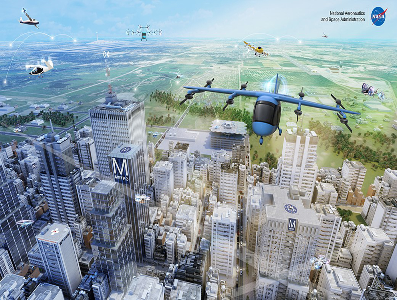
Vertiport Assessment and Mobility Operations System (VAMOS!)
The term Advanced Air Mobility (AAM) refers to a new mode of transportation utilizing highly automated airborne vehicles for transporting goods and/or people. The adoption of widespread use of AAM vehicles will necessitate a network of vertiports located throughout a geographical region. A vertiport refers to a physical structure for the departure, arrival, and parking/storage of AAM vehicles. NASA-developed Vertiport Assessment and Mobility Operations System (VAMOS!) enables identifying geographical locations suitable for locating a vertiport or assessing suitability of pre-selected locations. For example, suitability evaluation factors include zoning, land use, transit stations, fire stations, noise, and time-varying factors like congestion and demand.
The vertiport assessment system assigns suitability values to these factors based on user-input, and types, including location-based (e.g., proximity to mass transit stations), level-based (e.g., noise levels), characteristic-based (e.g., residential zoning), and time-based (e.g., demand). Based on user input, the system spreads a grid over the geographical area, specifies importance criteria and weights for scaling the impact of the suitability factors, and identifies specific sub-regions as candidate locations. The candidate sub-regions are shown on a user interface map overlay in a color-coded gradient that reflects the suitability strength for a sub-region. Vertiport locations are selected within these sub-regions. These candidate vertiport locations are refined by establishing feasibility of flight between them. VAMOS! includes a modeling component and a simulation component. The modeling component assists a user to identify one or more geographical locations at which a vertiport may be physically built. The simulation component of the technology displays, in real-time, the simulated operational behavior of AAM vehicles and in the context of their projected flight paths combined with data dynamically obtained from live sources. These data sources can be from the Federal Aviation Administration (FAA) or other private or public governing bodies, from one or more AAM vehicles in flight, and from weather sources.
Sensors

Receiver for Long-distance, Low-backscatter LiDAR
The NASA receiver is specifically designed for use in coherent LiDAR systems that leverage high-energy (i.e., > 1mJ) fiber laser transmitters. Within the receiver, an outgoing laser pulse from the high-energy laser transmitter is precisely manipulated using robust dielectric and coated optics including mirrors, waveplates, a beamsplitter, and a beam expander. These components appropriately condition and direct the high-energy light out of the instrument to the atmosphere for measurement. Lower energy atmospheric backscatter that returns to the system is captured, manipulated, and directed using several of the previously noted high-energy compatible bulk optics. The beam splitter redirects the return signal to mirrors and a waveplate ahead of a mode-matching component that couples the signal to a fiber optic cable that is routed to a 50/50 coupler photodetector. The receiver’s hybrid optic design capitalizes on the advantages of both high-energy bulk optics and fiber optics, resulting in order-of-magnitude enhancement in performance, enhanced functionality, and increased flexibility that make it ideal for long-distance or low-backscatter LiDAR applications.
The related patent is now available to license. Please note that NASA does not manufacturer products itself for commercial sale.
Aerospace

Aerodynamic Framework for Parachute Deployment from Aerial Vehicle
For rapid parachute deployment simulation, the framework and methodology provided by the simulation database uses parametrized aerodynamic data for a variety of environmental conditions, air taxi design parameters, and landing system designs. The database also includes a compilation of drag coefficients, thrust and lift forces, and further relevant aerodynamic parameters utilized in the simulated flight of a proposed air taxi. The database and framework can be constructed using simulated data that accounts for oscillatory breathing of parachutes. The methodology can further employ an overset grid of body-fitted meshes to accurately capture deployment of an internally-stored parachute, as well as descent of the air taxi and deployed parachute.
The systems and methods of the disclosed technology can be utilized with existing CFD solvers in a plug-and-play manner, such that the framework can be integrated to directly improve the performance of these solvers and the machines on which they are installed. The framework itself can employ parallelization to enable distributed solution of intensive CFD simulations to build a robust database of simulated data. Further, as up to 90% of computational time is spent in the calculation of aerodynamic parameters for use in coupled trajectory equations, the framework can significantly reduce the computational costs and design time for safe landing systems for air taxis. These reductions can lead to lower costs for design processes, while enabling rapid design and testing prior to physical prototyping.
Aerospace
Active Turbulence Suppression System for Electric Vertical Take-Off and Landing (eVTOL) vehicles
The Active Turbulence Suppression (ATS) system for electric Vertical Take-Off and Landing (eVTOL) vehicles employ existing lifting propellers to dampen instabilities during flight, such as Dutch-roll oscillations and other gust-induced oscillations. When a roll angle of an eVTOL aircraft has deviated or is about to deviate from a current stable aircraft state to an undesirable, unstable, and oscillating aircraft state, the ATS system queries a turbulence suppression database that stores a set of propeller speed profiles for mitigation a deviation of a given roll angle for a particular aircraft with specified propellers. Using this data, the eVTOL flight controller adjusts the speed of the propellers for a certain duration of time, according to the propeller speed profiles for mitigating the deviation. In models of aircraft with adjustable propeller angles, the database includes blade angle profiles for mitigating the effects of turbulent conditions. Timing and rate of propeller activation can be pre-computed using higher order computational modeling performed with NASA’s super computing resources. Because the data is pre-computed, the use of the ATS system onboard does not require significant computing resources to implement on eVTOL vehicles. The technology, a mechanism by which existing eVTOL propellers are leveraged to suppress gust-induced oscillations enables a safe and comfortable passenger experience at low-cost and without added hardware.
Propulsion

Efficient Megawatt-Scale Cable for Electric Aircraft Propulsion
Distilled to its core components, the cable is composed of either a flexible or rigid transmission line with integrated oil-based cooling. Instead of solid wire, current flows through small conductive tubes made of aluminum or copper, which are actively cooled by pump-driven oil flowing through them. Although these smaller conductors have higher resistance and generate more heat, the active cooling offsets this heat generation. This integrated design results in a cable with up to a tenfold improvement in weight per megawatt of power delivered compared to existing solutions.
The use of smaller conductive cables with active cooling reduces the temperature requirements for insulation because more current can be run through the cable. As such, voltage can be reduced, mitigating partial discharge issues, and making insulation an easier engineering challenge. Due to significant weight reductions, specialized duct work is no longer needed. A collection of junction, splicing, and termination components allow the cable to be built into a power and thermal bus to service multiple electrical components.
Initial tests demonstrated the ability to conduct 1,000 amps through actively cooled cables at lower mass than state-of-the-art alternatives, confirming feasibility for next-generation aircraft electrification. However, the cable has broad applications across all vehicle electrification where weight and thermal management are high priorities and is now available for patent licensing.
Aerospace
eVTOL UAS with Lunar Lander Trajectory
This NASA-developed eVTOL UAS is a purpose-built, electric, reusable aircraft with rotor/propeller thrust only, designed to fly trajectories with high similarity to those flown by lunar landers. The vehicle has the unique capability to transition into wing borne flight to simulate the cross-range, horizontal approaches of lunar landers. During transition to wing borne flight, the initial transition favors a traditional airplane configuration with the propellers in the front and smaller surfaces in the rear, allowing the vehicle to reach high speeds. However, after achieving wing borne flight, the vehicle can transition to wing borne flight in the opposite (canard) direction. During this mode of operation, the vehicle is controllable, and the propellers can be powered or unpowered.
This NASA invention also has the capability to decelerate rapidly during the descent phase (also to simulate lunar lander trajectories). Such rapid deceleration will be required to reduce vehicle velocity in order to turn propellers back on without stalling the blades or catching the propeller vortex. The UAS also has the option of using variable pitch blades which can contribute to the overall controllability of the aircraft and reduce the likelihood of stalling the blades during the deceleration phase.
In addition to testing EDL sensors and precision landing payloads, NASA’s innovative eVTOL UAS could be used in applications where fast, precise, and stealthy delivery of payloads to specific ground locations is required, including military applications. This concept of operations could entail deploying the UAS from a larger aircraft.
Aerospace

Wind-Optimal Cruise Airspeed Mode for Flight Management Systems (FMS)
The novel approach for optimizing airspeed for both actual and predicted wind conditions in electric Vertical Takeoff and Landing (eVTOL) aircraft with Distributed Electric Propulsion (DEP) systems includes the process of creating a lookup table for wind‐optimal airspeed as a function of wind magnitude, considering the direction of the wind relative to the cruise segment, considering the cruise altitude for an aircraft type, and incorporating the wind-optimal airspeed lookup table in the performance database for real‐time access by the Flight Management Systems (FMS) to predict wind-optimal airspeed at waypoints of the flight plan. The target wind‐optimal airspeed is updated in real-time throughout the cruise portion of a flight.
In a test of the wind-optimal airspeed targeting technique using a multi-rotor aircraft model, results obtained show benefits of flying at the wind‐optimal cruise airspeed compared to the best‐range airspeed. In headwind conditions, energy consumption was reduced by up to 7.5%, and flight duration was reduced by up to 28%. Under uncertain wind magnitudes, flying at wind-optimal airspeed offered lower variability and higher predictability in energy consumption than flying at best‐range airspeed.
Aerospace

Optimized Airfoil Design for Aerial Flight Vehicles in Low-Reynolds Flight
This invention, developed under the Rotor Optimization for the Advancement of Mars eXploration (ROAMX) project, provides a method for optimizing airfoil geometries for aerial flight vehicles generally, and can also specifically optimize airfoil geometries for operating in Martian or other low Reynolds number environments. The method introduces a new “ROAMX parameterization” that defines geometric constraints, such as camber node count and the number and order of Bézier curve segments, to generate candidate airfoil shapes. A genetic algorithm evaluates these shapes against multiple objectives and iteratively selects the best-performing designs, converging on a Pareto-optimal front. This enables simultaneous optimization of metrics such as maximizing lift and minimizing drag. Using the ROAMX 1301 parameterization, the method produced an airfoil with lift to drag ratio improvements of up to 42% over the outboard airfoil used on the Mars Helicopter Ingenuity, representing a significant performance gain.

