Rapid Aero Modeling for Computational Experiments
Information Technology and Software
Rapid Aero Modeling for Computational Experiments (LAR-TOPS-382)
Powerful tool streamlines modeling and design of complex aircraft
Overview
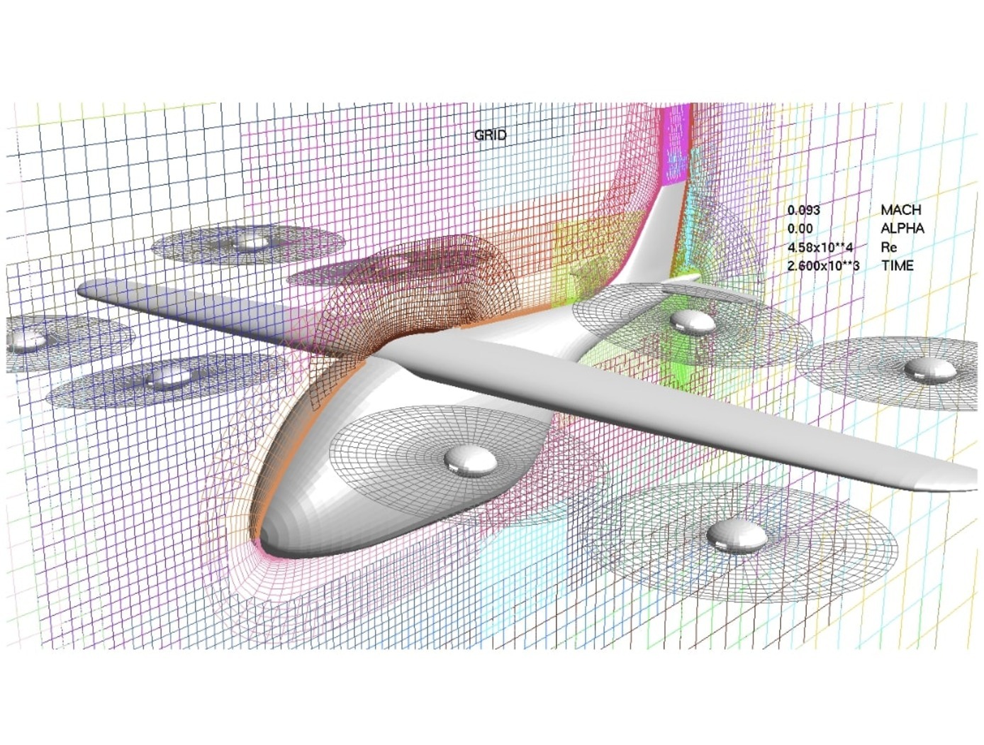
Aerodynamic modeling plays a critical role in the development of new aircraft, particularly for innovative designs aimed at urban air mobility (UAM) applications. This includes electric vertical takeoff and landing (eVTOL) aircraft, which combine features of conventional aircraft and rotorcraft. Such advanced designs offer a host of new capabilities but also introduce significantly increased complexity relative to conventional aircraft, including intricate nonlinear aerodynamic responses as well as interactions between propulsion and aerodynamic control systems. For the flight dynamics and controls disciplines, this added complexity renders detailed computational fluid dynamics (CFD) models unable to produce results fast enough for flight simulations.
To address this challenge, NASA developed Rapid Aero Modeling for Computational Experiments (RAM-C), a software-implemented method capable of generating aerodynamic models that capture the important features of complex aircraft in a manner suitable for flight dynamics simulations. RAM-C can be thought of as a “wrapper” around computational (e.g., CFD) software, which it provides specific test inputs to, and receives aerodynamic measurements as outputs from. The input-output data are used to identify mathematical models and evaluate their statistical performance and fidelity. In essence, this NASA invention automates and streamlines the design phase for innovative aircraft while limiting computational requirements.
The Technology
RAM-C interfaces with computational software to provide test logic and manage a unique process that implements three main bodies of theory: (a) aircraft system identification (SID), (b) design of experiment (DOE), and (c) CFD. SID defines any number of alternative estimation methods that can be used effectively under the RAM-C process (e.g., machine learning techniques, regression, neural nets, fuzzy modeling, etc.). DOE provides a statistically rigorous, sequential approach that defines the test points required for a given model complexity. Typical DOE test points are optimized to reduce either estimation error or prediction error. CFD provides a large range of fidelity for estimating aircraft aerodynamic responses. In initial implementations, NASA researchers “wrapped” RAM-C around OVERFLOW, a NASA-developed high-fidelity CFD flow solver. Alternative computational software requiring less time and computational resources could be also utilized.
RAM-C generates reduced-order aerodynamic models of aircraft. The software process begins with the user entering a desired level of fidelity and a test configuration defined in terms appropriate for the computational code in use. One can think of the computational code (e.g., high-fidelity CFD flow solver) as the “test facility” with which RAM-C communicates with to guide the modeling process. RAM-C logic determines where data needs to be collected, when the mathematical model structure needs to increase in order, and when the models satisfy the desired level of fidelity.
RAM-C is an efficient, statistically rigorous, automated testing process that only collects data required to identify models that achieve user-defined levels of fidelity – streamlining the modeling process and saving computational resources and time. At NASA, the same Rapid Aero Modeling (RAM) concept has also been applied to other “test facilities” (e.g., wind tunnel test facilities in lieu of CFD software).
 process. For RAM-C, the \"test facility\" is a computational software program, such as NASA's OVERFLOW CFD flow solver.")
Benefits
- Suitable for highly complex aircraft: RAM-C is suitable for aerodynamic modeling of modern UAM aircraft designs (e.g., eVTOL) with significantly increased numbers of factors relative to conventional aircraft.
- Increased experimental efficiency: RAM-C offers increased efficiency of aerodynamic modeling for complex aircraft by limiting data collection requirements and automating the modeling process (while allowing for user supervision).
- Provides test guidance: RAM-C effectively guides computational code-based tests to obtain high-fidelity, statistically rigorous aircraft models – starting with experimental design, through test execution, and in final model analysis.
- Flexibility: RAM-C can be adapted for real-time, online, or batch processing approaches, depending on user needs and infrastructure.
- OVERFLOW availability: RAM-C has been implemented with NASA’s Overset Grid CFD Flow Solver (OVERFLOW) software. OVERFLOW is available to U.S. persons and companies via NASA’s software catalog.
Applications
- Aircraft design & simulation: RAM-C was developed as a tool to efficiently obtain aerodynamic models of complex aircraft during computational investigations in an automated or guided manner. These aerodynamic models can then be used for flight dynamics studies and simulations (i.e., aircraft design). RAM-C may be particularly useful in the design of UAM aircraft (e.g., eVTOL) or other aircraft with significant complexity and aerodynamic nonlinearities.
Technology Details
Information Technology and Software
LAR-TOPS-382
LAR-19724-1
Patent Pending
"Rapid Aero Modeling for Urban Air Mobility Aircraft in Computational Experiments." Murphy, Patrick et al., 2021, https://ntrs.nasa.gov/citations/20205010446
"Rapid Aero Modeling of a Lift+Cruise UAM Configuration for Stability & Control Using Overset Grid CFD." Buning, Pieter et al., 2022, https://ntrs.nasa.gov/citations/20220015534
"Preliminary Steps in Developing Rapid Aero Modeling Technology." Murphy, Patrick et al., 2020, https://ntrs.nasa.gov/citations/20200003103
"Rapid Aero Modeling for Urban Air Mobility Aircraft in Wind-Tunnel Tests." Murphy, Patrick et al., 2021, https://ntrs.nasa.gov/citations/20205010453
Full-Envelope Aero-Propulsive Model Identification for Lift+Cruise Aircraft Using Computational Experiments." Simmons, Benjamin et al., 2021, https://ntrs.nasa.gov/citations/20210017459
Similar Results

Aerodynamic Framework for Parachute Deployment from Aerial Vehicle
For rapid parachute deployment simulation, the framework and methodology provided by the simulation database uses parametrized aerodynamic data for a variety of environmental conditions, air taxi design parameters, and landing system designs. The database also includes a compilation of drag coefficients, thrust and lift forces, and further relevant aerodynamic parameters utilized in the simulated flight of a proposed air taxi. The database and framework can be constructed using simulated data that accounts for oscillatory breathing of parachutes. The methodology can further employ an overset grid of body-fitted meshes to accurately capture deployment of an internally-stored parachute, as well as descent of the air taxi and deployed parachute.
The systems and methods of the disclosed technology can be utilized with existing CFD solvers in a plug-and-play manner, such that the framework can be integrated to directly improve the performance of these solvers and the machines on which they are installed. The framework itself can employ parallelization to enable distributed solution of intensive CFD simulations to build a robust database of simulated data. Further, as up to 90% of computational time is spent in the calculation of aerodynamic parameters for use in coupled trajectory equations, the framework can significantly reduce the computational costs and design time for safe landing systems for air taxis. These reductions can lead to lower costs for design processes, while enabling rapid design and testing prior to physical prototyping.

Fixed Wing Angle eVTOL
While previous eVTOLs often require a near 90° wing tilt to position propellers in an optimal location to generate vertical force for takeoff, NASA has taken a very different approach. NASA's design instead uses a slight wing angle and large flaps designed to deflect slipstream generated by the propellers to create a net positive force in the vertical direction, all while preventing forward movement. This unique configuration allows for takeoff and landing operations without the need for near 90° wing tilt angles. After takeoff, the transition to forward flight only requires a slight change in attitude of the vehicle and retraction of the flaps. Similar solutions require large changes in attitude to accomplish this transition which is often undesirable, especially for air taxi operations that involve passengers.
Given the effectiveness of this configuration for generating upward force, the requirement for wing angle tilt has been reduced from near 90° to approximately 15° during takeoff. Further iterations may reduce this requirement even further to 0°. By eliminating the need for near 90° wing tilt, NASA's eVTOL design removes the need for mechanisms to perform active tilting of the wings or rotors, reducing system mass and thereby improving performance. Flaps represent the only components that require actuation for takeoff and landing operations.
Innovators at NASA leveraged the Langley Aerodrome 8 (LA-8), a modular testbed vehicle that allows for rapid prototyping and testing of eVTOLs with various configurations, to design and test this novel concept.

Active Turbulence Suppression System for Electric Vertical Take-Off and Landing (eVTOL) vehicles
The Active Turbulence Suppression (ATS) system for electric Vertical Take-Off and Landing (eVTOL) vehicles employ existing lifting propellers to dampen instabilities during flight, such as Dutch-roll oscillations and other gust-induced oscillations. When a roll angle of an eVTOL aircraft has deviated or is about to deviate from a current stable aircraft state to an undesirable, unstable, and oscillating aircraft state, the ATS system queries a turbulence suppression database that stores a set of propeller speed profiles for mitigation a deviation of a given roll angle for a particular aircraft with specified propellers. Using this data, the eVTOL flight controller adjusts the speed of the propellers for a certain duration of time, according to the propeller speed profiles for mitigating the deviation. In models of aircraft with adjustable propeller angles, the database includes blade angle profiles for mitigating the effects of turbulent conditions. Timing and rate of propeller activation can be pre-computed using higher order computational modeling performed with NASA’s super computing resources. Because the data is pre-computed, the use of the ATS system onboard does not require significant computing resources to implement on eVTOL vehicles. The technology, a mechanism by which existing eVTOL propellers are leveraged to suppress gust-induced oscillations enables a safe and comfortable passenger experience at low-cost and without added hardware.

Multi-Objective Flight Control Optimization Framework
Composite materials are being used in aerospace design because of their high strength-to-weight ratio. On modern airplanes, composite wings offer a greater degree of aerodynamic efficiency due to weight savings, but at the same time introduce more structural flexibility than their aluminum counterparts. Under off-design flight conditions, changes in the wing shape due to structural flexibility cause the wing aerodynamics to be non-optimal. This effect could offset any weight saving benefits realized by the composite wings. Structural flexibility could also cause adverse interactions with flight control and structural vibration which can compromise aircraft stability, pilot handling qualities, and passenger ride quality. NASA Ames Research Center has developed a novel technology that employs a new multi-objective flight control optimization framework to achieve multiple control objectives simultaneously. This technology leverages the availability of distributed flight control surfaces in modern transports. The multi-objective flight control technology comprises the following objectives all acting in a synergistic manner: 1) traditional stability augmentation and pilot command-following flight control, 2) drag minimization, 3) aeroelastic mode suppression, 4) gust load alleviation, and 5) maneuver load alleviation. Each of these objectives can be a major control system design in its own right. Thus, the multi-objective flight control technology can effectively manage the complex interactions of the individual single-objective flight control system design and take into account multiple competing requirements to achieve optimal flight control solutions that have the best compromise for these requirements. In addition, a real- time drag minimization control strategy is included in the guidance loop. This feature utilizes system identification methods to estimate aerodynamic parameters for the on-line optimization. The aerodynamic parameters are also used in the multi-objective flight control for drag minimization and maneuver/ gust load alleviation control.

Co-Optimization of Blunt Body Shapes for Moving Vehicles
Vehicles designed for purposes of exploration of the planets and other atmospheric bodies in the Solar System favor the use of mid-Lift/Drag blunt body geometries. Such shapes can be designed so as to yield favorable hypersonic aerothermodynamic properties for low heating and hypersonic aerodynamic properties for maneuverability and stability. The entry trajectory selected influences entry peak heating and integrated heating loads which in turn influences the design of the thermal protection system. A nominal is used to compare each shape considered. The vehicle will be subject to both launch and entry loading along with structural integrity constraints that may further influence shape design. Further, such vehicles must be sized so as to fit on existing or realizable launch vehicles, often within existing launch payload shroud constraints.

