Additively Manufactured Oscillating Heat Pipe for High Performance Cooling in High Temperature Applications
mechanical and fluid systems
Additively Manufactured Oscillating Heat Pipe for High Performance Cooling in High Temperature Applications (TOP2-316)
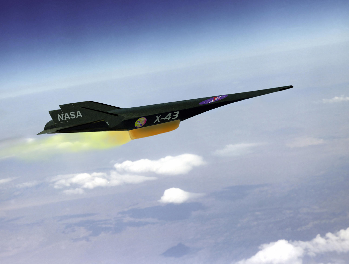
Integrated Thermal Solution for Hypersonic Wing Leading Edge Applications
Overview
High performance cooling techniques for enhanced heat transfer for high temperature applications are increasingly important, particularly in the field of aerospace engineering. For example, leading edges of wings on hypersonic vehicles may reach upwards of 2000 C, and such heat quickly degrades the leading edge. Conventional heat pipes contain bends or welds in the material that can compromise the structural integrity of the wing leading edge. Oscillating Heat Pipes (OHPs) are a newer form of heat pipe which can cool more efficiently than traditional heat pipes, and are easier to manufacture. NASA Ames Research Center has developed a novel additive manufacturing technique to manufacture OHPs from Refractory High Entropy Alloys (RHEAs). These OHPs are effective in hypersonic vehicles with sharp, shape-stable wing leading edges. Additive manufacturing allows for enhancements such as alternating-diameter channels, allowing for changes in pressure.
The Technology
The advent of additive manufacturing makes available new and innovative integrated thermal management systems, including integrating an oscillating Heat Pipe (OHP) into the leading edge of a hypersonic vehicle for rapid dissipation of large quantities of heat. OHPs have interconnected capillary channels filled with a working fluid that forms a train of liquid plugs and vapor bubbles to facilitate rapid heat transfer. Multiple additive manufacturing techniques may be used, including powder bed fusion, binder jetting, metal material extrusion, directed energy deposit, sheet lamination, ultrasonic, and electrochemical techniques. These high performance OHPs can be made with materials such as Refractory High Entropy Alloys (RHEAs) that can withstand high temperature applications. The structure of the OHP can be integrated into the constructed leading edge. The benefits include a heat transport capacity of 10 to 100 times greater than before. Integrated OHPs avoid the bends or welds in traditional heat pipes, especially at the locations where the highest thermal stresses might cause thermal-structural failure of a leading edge. Alternating the diameters of the OHP channels alleviate start-up issues typically found in liquid metal oscillating heat pipe designs in high temperature applications by aiding in the instigation of a circulating flow due to multiple forces acting upon the working fluid.
")
Benefits
- Heat dissipation for leading edges of hypersonic vehicles
- Heat transport capacity of 10 to 100 times greater than currently employed solutions such as reinforced carbon-carbon leading edge cooling technologies or traditional heat pipes
- Fully passive and reusable
- Increases the ability to withstand body forces by an order of magnitude, and may be used at much higher Mach numbers
- Avoids thermal structural failure caused by bends and welds of traditional heat pipes
- Reduced form factor that allows better incorporation into sharp geometries
- Usable for any system that requires rapid dissipation of heat
Applications
- Efficient heat transfer devices that can operate at high temperatures
- Hypersonic wing leading edges
- Nuclear thermal propulsion
- Plasma facing materials in fusion devices
- Re-entry vehicles and shuttles
- Processor/microchip thermal straps
- Conduction cooled circuit card heat sinks
- Lithium-ion battery packs
- Radio-frequency device heat spreaders
- Energy recovery heat exchangers
- Optical equipment heat sinks
Technology Details
mechanical and fluid systems
TOP2-316
ARC-18625-1
Patent Pending
Similar Results

Cladding and Freeform Deposition for Coolant Channel Closeout
LWDC technology enables an improved channel wall nozzle with an outer liner that is fused to the inner liner to contain the coolant. It is an additive manufacturing technology that builds upon large-scale cladding techniques that have been used for many years in the oil and gas industry and in the repair industry for aerospace components. LWDC leverages wire freeform laser deposition to create features in place and to seal the coolant channels. It enables bimetallic components such as an internal copper liner with a superalloy jacket. LWDC begins when a fabricated liner made from one material, Material #1, is cladded with an interim Material #2 that sets up the base structure for channel slotting. A robotic and wire-based fused additive welding system creates a freeform shell on the outside of the liner. Building up from the base, the rotating weld head spools a bead of wire, closing out the coolant channels as the laser traverses circumferentially around the slotted liner. This creates a joint at the interface of the two materials that is reliable and repeatable. The LWDC wire and laser process is continued for each layer until the slotted liner is fully closed out without the need for any filler internal to the coolant channels. The micrograph on the left shows the quality of the bond at the interface of the channel edge and the closeout layer; on the right is a copper channel closed out with stainless.

Printable Heat Shield Formulations Advance Spacecraft Construction
One inner insulative layer, and one outer robust ablative layer comprise the AMTPS technology. When applying the heat shield to the surface of a spacecraft, the insulative layer is printed first and primarily functions to reduce the amount of heat soak into the vehicle. The formulation of the insulative layer has a slightly lower density (as compared to the robust layer) and is adjusted using a differing constituent ratio of phenolic and/or glass microballoon material. Both formulations combine a phenolic resin with various fillers to control pre- and post-cure properties that can be adjusted by varying the carbon and/or glass fiber content along with rheology modifiers to enhance the fluid flow for deposition systems.
The robust layer is applied next and functions as the ablative layer that ablates away or vaporizes when subjected to extremely high temperatures such as those achieved during atmospheric entry. The formulation of the robust layer produces a gas layer as it vaporizes in the extreme heat that acts as a boundary layer. This boundary prevents heat from further penetrating the remaining robust material by pushing away the even hotter shock layer. The shock layer is a region of super-heated compressed gas, positioned in front of the Earth-facing bottom of the spacecraft during atmospheric entry, that results from the supersonic shockwave generated.
Commercial space applications for this AMTPS technology include use on any spacecraft that transits a planetary or lunar atmosphere such as Mars or Saturn’s moon Titan. Additionally, the invention may be useful for launch system rockets to provide heat shielding from atmospheric reentry or to protect ground equipment on the launch pad from rocket exhaust plumes. As the number of government and commercial space missions to primary Earth orbits, the Moon, and the Solar System increase, there will be a growing need for cost-effective, on-demand, and timely fabrication of heat shields for space-related activities.
AMTPS Formulations – Insulative and Robust Variation is at a technology readiness level (TRL) 5 (component and/or breadboard validation in laboratory environment) and is now available for patent licensing. Please note that NASA does not manufacture products itself for commercial sale.

New Concepts in Film Cooling for Turbine Blades
In one of NASA Glenn's innovations, a shaped recess can be formed on a surface associated with fluid flow. Often V-shaped, this shaped recess can be configured to create or induce fluid effects, temperature effects, or shedding effects. For example, the shaped recess can be paired (upstream or downstream) with a cooling channel. The configuration of the shaped recess can mitigate the lift-off or separation of the cooling jets that are produced by the cooling channels, thus keeping the cooling jets trained on turbine blades and enhancing the effectiveness of the film-cooling process. The second innovation produced to improve film cooling addresses problems that occur when high-blowing ratios, such as those that occur during transient operation, threaten to diminish cooling effectiveness by creating jet detachment. To keep the cooling jet attached to the turbine blade, and also to spread the jet in the spanwise direction, NASA Glenn inventors have successfully used cooling holes that reduce loss by blowing in the upstream direction. In addition, fences may be used upstream of the holes to bend the cooling flow back toward the downstream direction to further reduce mixing losses. These two innovations represent a significant leap forward in making film cooling for turbine blades, and therefore the operation of turbine engines, more efficient.

Woven Thermal Protection System
Going farther, faster and hotter in space means innovating how NASA constructs the materials used for heat shields. For HEEET, this results in the use of dual-layer, three-dimensional, woven materials capable of reducing entry loads and lowering the mass of heat shields by up to 40%. The outer layer, exposed to a harsh environment during atmospheric entry, consists of a fine, dense weave using carbon yarns. The inner layer is a low-density, thermally insulating weave consisting of a special yarn that blends together carbon and flame-resistant phenolic materials. Heat shield designers can adjust the thickness of the inner layer to keep temperatures low enough to protect against the extreme heat of entering an atmosphere, allowing the heat shield to be bonded onto the structure of the spacecraft itself. The outer and inner layers are woven together in three dimensions, mechanically interlocking them so they cannot come apart. To create this material, manufacturers employ a 3-D weaving process that is similar to that used to weave a 2-D cloth or a rug. For HEEET, computer-controlled looms precisely place the yarns to make this kind of complex three-dimensional weave possible. The materials are woven into flat panels that are formed to fit the shape of the capsule forebody. Then the panels are infused with a low-density version of phenolic material that holds the yarns together and fills the space between them in the weave, resulting in a sturdy final structure. As the size of each finished piece of HEEET material is limited by the size of the loom used to weave the material, the HEEET heat shield is made out of a series of tiles. At the points where each tile connects, the gaps are filled through inventive designs to bond the tiles together.

High-Performance, Lightweight, Easy-to-Fabricate Heat Exchanger
Researchers at JPL have developed, built, and tested an innovative heat exchanger that offers reduced thermal expansion, increased structural strength, low pressure drop, and improved thermal performance while lowering the weight associated with typical heat exchangers. This innovation would benefit the commercial thermoelectric generator, aircraft, and industrial processing (i.e., glass, steel, petrochemical, cement, aluminum) industries by improving energy management/efficiency, reducing carbon dioxide emissions, and increasing system durability due to the reduced stress from thermal expansion.
The Problem
Thermoelectric generator systems require high-performance hot-side and cold-side heat exchangers to provide the temperature differential needed to transfer thermal energy while withstanding temperatures up to 650 °C. Because the hot-side heat exchangers must have a high heat flux, they are often made of metals such as stainless steel or Inconel® alloys. Although these materials can operate at high temperatures, resist corrosion, and are chemically stable, they also have several drawbacks: (1) Their lower thermal conductivity negatively affects their thermal performance. (2) Their higher thermal expansion leads to stresses that compromise system structural integrity. (3) Their high mass/volume reduces the power density of generator systems into which they are integrated. As a result, they are difficult to integrate into viable energy recovery systems. They also make the systems unreliable, non-durable, and susceptible to failures caused by thermal-structural expansion.
The Solution
JPL researchers chose to replace the metal in traditional heat exchangers with graphite, which offers an improved conductivity-to-density ratio in thermal applications as well as a low coefficient of thermal expansion. In addition, they used a mini-channel design to further increase thermal performance. Combining more advanced materials with the innovative thermal design has yielded significant improvements in performance. For example, a 200-cm3, 128-g version of JPL's exchanger successfully transported 1,100 W from exhaust at nearly 550 °C with approximately 20 W/cm2 thermal flux and a pressure drop of only 0.066 psi.
JPL's technology combines lightweight, high-strength graphite material with a mini-channel design that offers high thermal performance. Further development and testing are underway.
Inconel is a registered trademark of Special Materials Corporation.

