Search
PATENT PORTFOLIO

Space Weather Database Of Notifications, Knowledge, Information (DONKI)
The Space Weather DONKI builds a catalog of past, present, ongoing, and expected Space Weather events. The catalog contains both forecaster logs and notifications. DONKI version 2.0 of has a comprehensive web-service API access for users to obtain space weather events stored in the database. The database consists of a backend and a web application. The database uses a framework that allows modularization of code and promotes code reuse.
DONKI is the first application to allow space weather scientists to store all space weather events in one centralized data center. The comprehensive database provides search capability to support scientists allowing them to look into linkages, relationships, and cause-and-effects between space weather activities.

Visual Inspection Posable Invertebrate Robot (VIPIR)
Initially developed as a close quarters inspection tool capable of accessing hard to reach, tight, or visibly restricted, areas of satellites, the VIPIR system can be used to remotely inspect inaccessible locations such as behind a sheet of thermal blanketing material, into a satellites plumbing, or perhaps even deep inside the otherwise unreachable crevasses of a spacecraft bus. The VIPIR system incorporates a number of subassemblies for incredible operational freedom and capabilities for imaging and dissemination of componentry.
VIPIR’s Video Borescope Assembly (VBA) is a flexible snake-camera capable of multidirectional articulations, making steering and control simple and intuitive for an operator. The VBA also includes at least one imaging sensor and lighting to see in dark, confined spaces. Real-time, high-resolution visual information can be fed back to an operator for live analysis. A reel system extends and retracts the VBA with the use of a spool, and includes position indicators for deployment tracking. The Tendon Management System (TMS), not unlike human tendons, utilizes pulleys and tensioners to articulate the VBA in the confined spaces. A seal system ensures the VBA is free of contamination.
VIPIR underwent space-based testing on the ISS during the Robotic Refueling Phase 2 (RRM-2) mission designed to showcase and test several NASA advanced robotic satellite servicing technologies. During this mission, VIPIR demonstrated state-of-the-art near and midrange inspection capabilities. NASA’s VIPIR system is available for licensing to industry, and may be desirable to companies focused on satellite servicing, on-orbit assembly, and other applications requiring detailed inspection of assets in space.
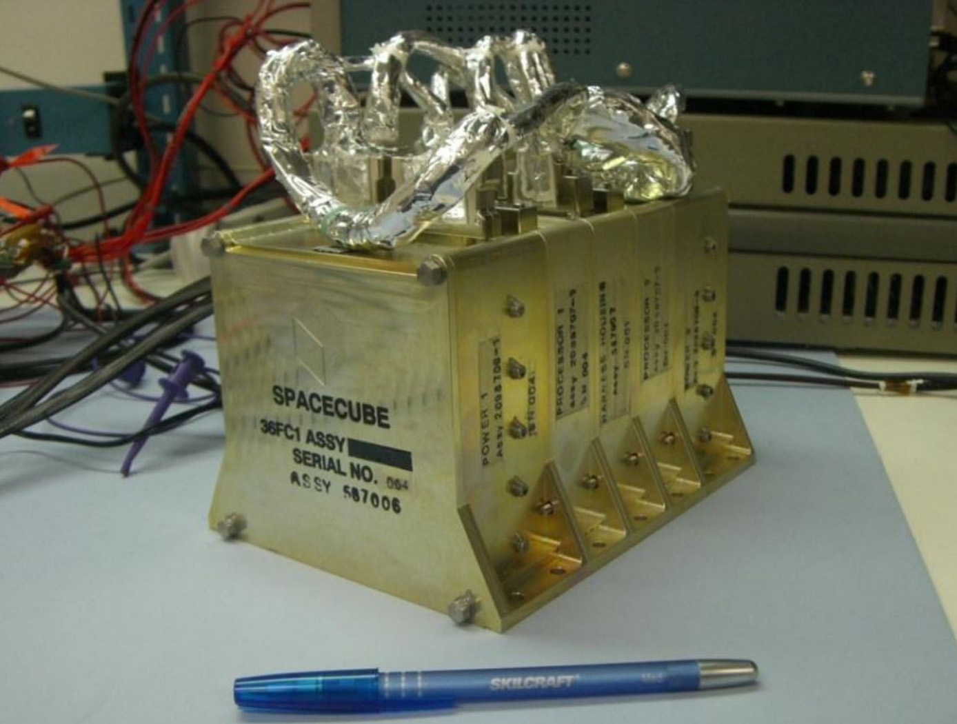
SpaceCube
Next generation instruments are capable of producing data at rates of 108 to 1011 bits per second, and both their instrument designs and mission operations concepts are severely constrained by data rate/volume. SpaceCube is an enabling technology for these next generation missions.
SpaceCube has demonstrated enabling capabilities in Earth Science, Planetary, Satellite Servicing, Astrophysics and Heliophysics prototype applications such as on-board product generation, intelligent data volume reduction, autonomous docking/landing, direct broadcast products, and data driven processing with the ability to autonomously detect and react to events. SpaceCube systems are currently being developed and proposed for platforms from small CubeSats to larger scale experiments on the ISS and standalone free-flyer missions, and are an ideal fit for cost constrained next generation applications due to the tremendous flexibility (both functional and interface compatibility) provided by the SpaceCube system.

STELLA-1.2
The STELLA-1.2 base unit includes a microcontroller, GPS, BME280 (temperature, pressure, humidity), and rotary control with display. Sensor modules include:
• Spectrometer: 18-band VNIR from 410–940nm, UV, light, IR, lidar
• Air Quality: CO₂ (SCD-40), PM2.5/PM10 (PMSA003I), methane
• Expandability: More modules via magnetic couplers and CircuitPython menu additions

TerraROVER
The TerraROVER’s core functionality is centered around its electric propulsion system, enabling it to traverse various outdoor environments. Its drive system consists of electric motors and gearboxes that provide controlled speed and maneuverability. The remote-control interface allows users to adjust speed and direction, making it an effective platform for training and testing mobility systems. For advanced applications, the TerraROVER can be adapted for pre-programmed or autonomous navigation, expanding its use in robotics and automation research.
A key design feature of the TerraROVER is its adaptability for sensor integration. It includes mounting provisions for miniaturized sensors capable of capturing environmental data such as temperature, GPS location, and visual imagery. The platform supports both onboard data logging and real-time transmission, making it suitable for field studies, distributed sensing applications, and educational experiments. Fabrication is streamlined through the use of 3D-printed components, allowing for cost-effective production and easy assembly in classroom or research settings. Currently at Technology Readiness Level (TRL) 7, the system has been successfully demonstrated in an operational environment and is available for patent licensing.
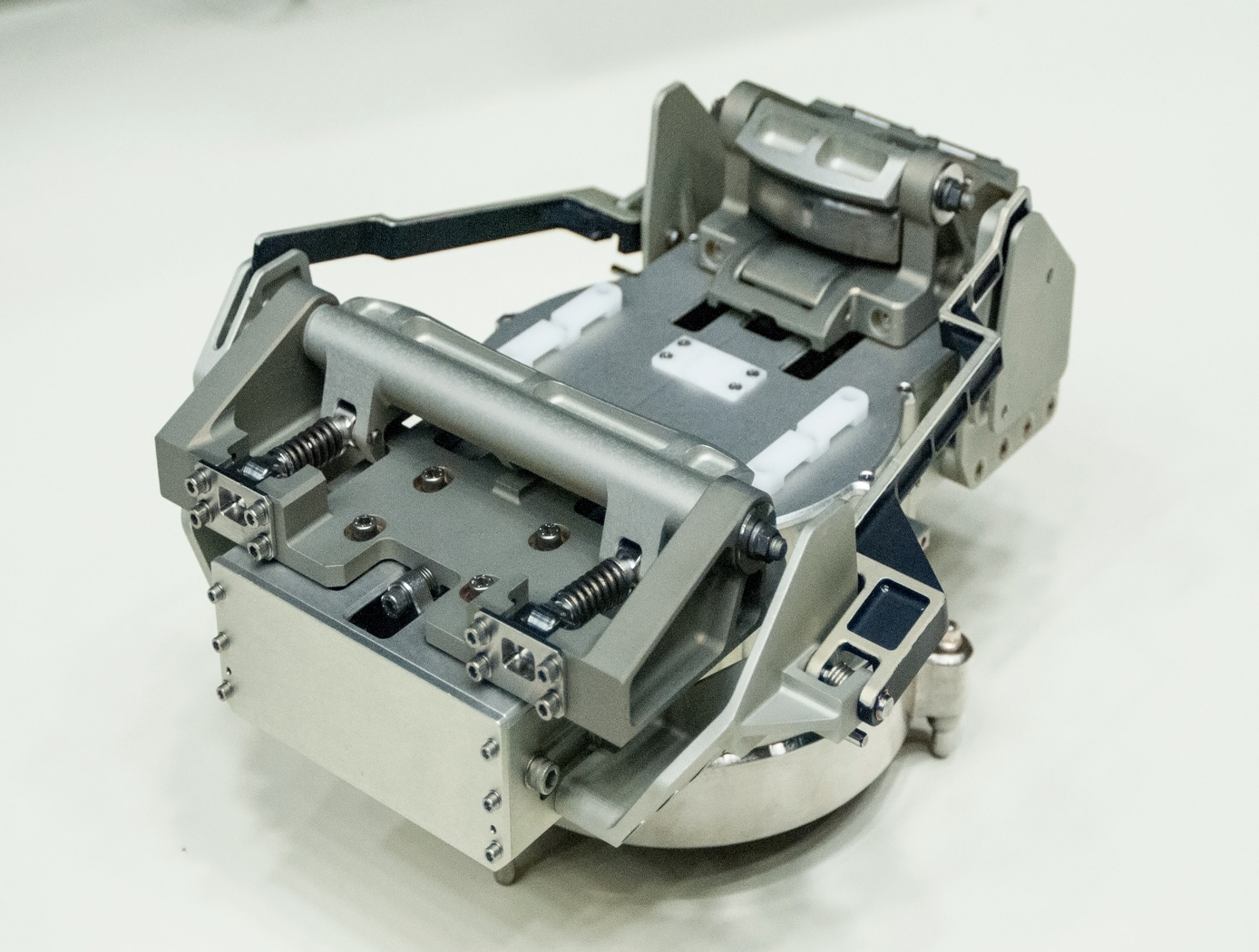
Robotic gripper for satellite capture and servicing
The Gripper is located at the end of a robotic system consisting of a robotic arm equipped with a Tool Drive or End Effector comprising the input actuator to the Gripper as well as the structural, power and data link between the Gripper and the robotic arm. In a notional concept of operations, a Servicer would approach the Client in an autonomous rendezvous and capture (AR&C) maneuver. When the Servicers sensor suite confirms that the distance, orientation, and relative translational and angular rates with respect to the Client are within an acceptable range, the Servicer enables the grasping sequence, where the robotic arm, equipped with Gripper, extend forward to the Client. When the Gripper/ Servicer sensors indicate that the Client marman ring is sufficiently within the capture range of the Gripper, a trigger signal is sent to the robot control system that commands the End Effector to drive the mechanism of the Gripper and affect closure around the marman ring. The Gripper consists of a pair of jaws which are driven by an internal transmission. The transmission receives input torque from the End Effector and converts the torque to appropriate motion of the jaws.
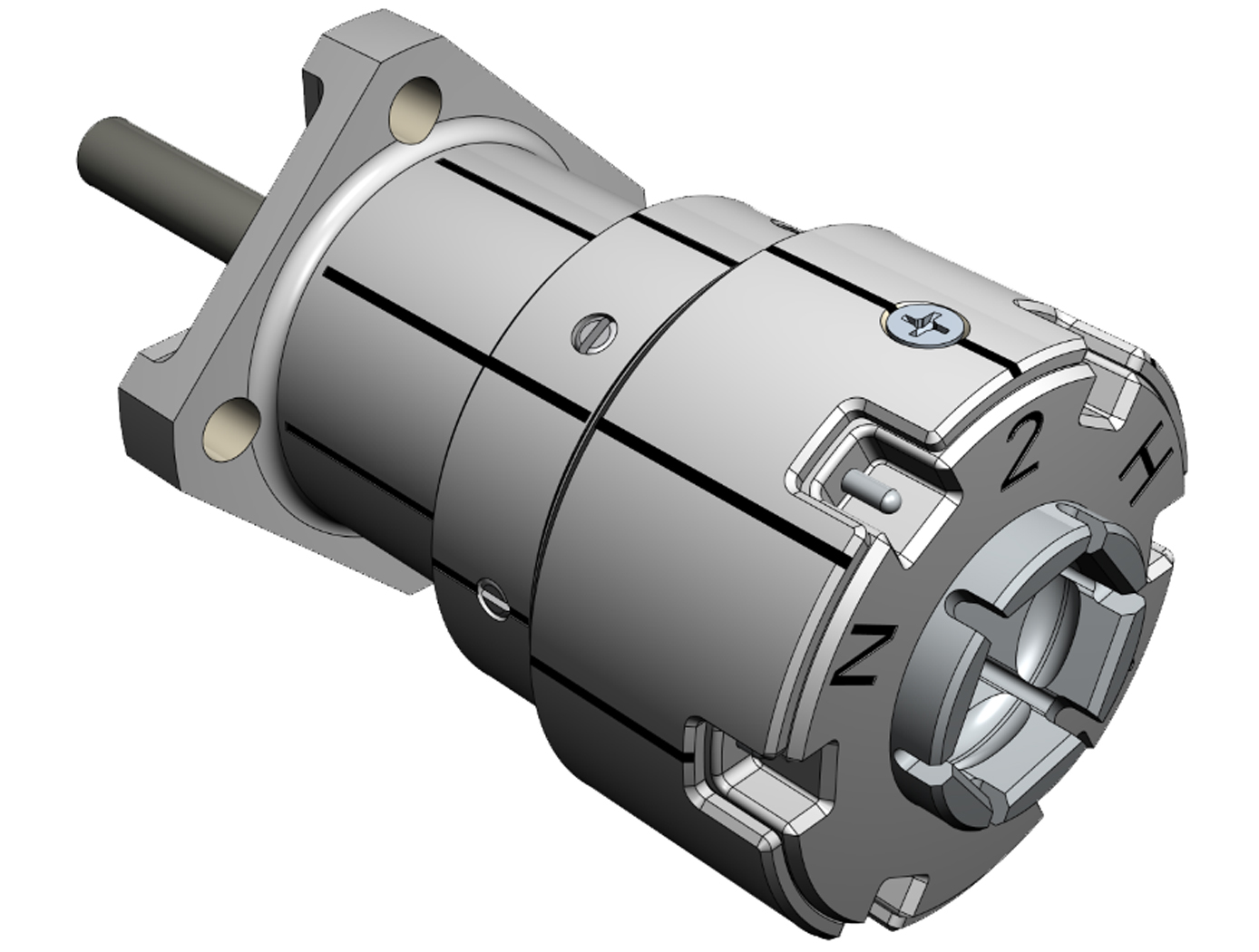
Cooperative Service Valve for In-orbit Cooperative Satellite Fueling
The CSV replaces a standard spacecraft Fill and Drain Valve to facilitate cooperative servicing. The CSV offers various advantages over standard service valves: a robotic interface, three individually actuated seals, a self-contained anti-back drive system, and built-in thermal isolation. When mounted to a spacecraft as designed, the CSV transfers all operational and induced robotic loads to the mounting structure. An anti-back drive mechanism prevents the CSV seal mechanism from inadvertent actuation. Alignment marks, thermal isolation, and a mechanical coupling capable of reacting operational and robotic loads optimize the CSV for tele-robotic operations. Unique keying of the mating interface prevents mixing of media where more than one configuration of the CSV is used. Color-coding and labels are also used to prevent operator error.
The CSV has four configurations for different working fluids, all with essentially unchanged geometry and mechanics.
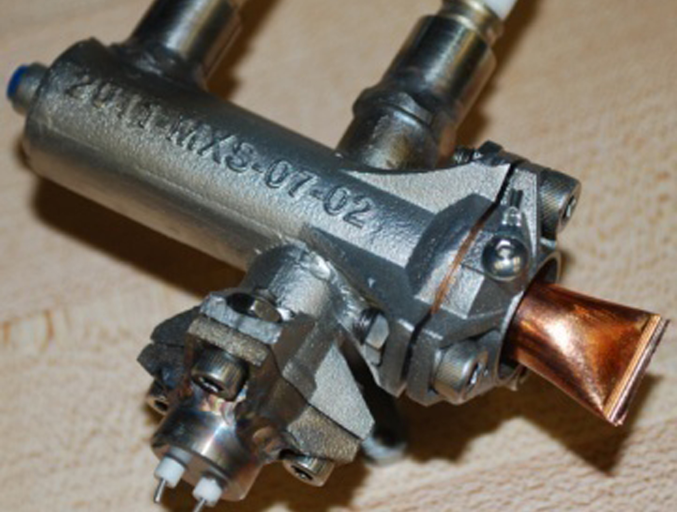
Miniaturized High-Speed Modulated X-Ray Source (MXS)
The MXS produces electrons by shining UV light from an LED onto a photocathode material such as magnesium. The electrons are then accelerated across several kV and into a chosen target material; deceleration produces X-rays characteristic of the target. The MXS uses an electron multiplier for high X-ray production efficiency.
The MXS is more compact, rugged, and power-efficient than standard X-ray sources. It can be manufactured using commercially available components and 3D printed housing, resulting in a low cost to manufacture. Unlike traditional X-ray sources, the MXS does not require a filament or vacuum and cooling systems. Most importantly, enabling rapid and arbitrary modulation allows using X-rays in the time domain, a new dimension to X-ray applications.

FlashPose: Range and intensity image-based terrain and vehicle relative pose estimation algorithm
Flashpose is the combination of software written in C and FPGA firmware written in VHDL. It is designed to run under the Linux OS environment in an embedded system or within a custom development application on a Linux workstation. The algorithm is based on the classic Iterative Closest Point (ICP) algorithm originally proposed by Besl and McKay. Basically, the algorithm takes in a range image from a three-dimensional imager, filters and thresholds the image, and converts it to a point cloud in the Cartesian coordinate system. It then minimizes the distances between the point cloud and a model of the target at the origin of the Cartesian frame by manipulating point cloud rotation and translation. This procedure is repeated a number of times for a single image until a predefined mean square error metric is met; at this point the process repeats for a new image.
The rotation and translation operations performed on the point cloud represent an estimate of relative attitude and position, otherwise known as pose.
In addition to 6 degree of freedom (DOF) pose estimation, Flashpose also provides a range and bearing estimate relative to the sensor reference frame. This estimate is based on a simple algorithm that generates a configurable histogram of range information, and analyzes characteristics of the histogram to produce the range and bearing estimate. This can be generated quickly and provides valuable information for seeding the Flashpose ICP algorithm as well as external optical pose algorithms and relative attitude Kalman filters.
View more patents

