Search
PATENT PORTFOLIO
Instrumentation
From research and development to industrial and commercial applications, NASA's instrumentation technology can help you unlock new insights, improve efficiency, and drive innovation. Whether you're looking to advance your understanding of the cosmos or simply want to optimize your operations, NASA's instrumentation technology could be the perfect partner for your journey.
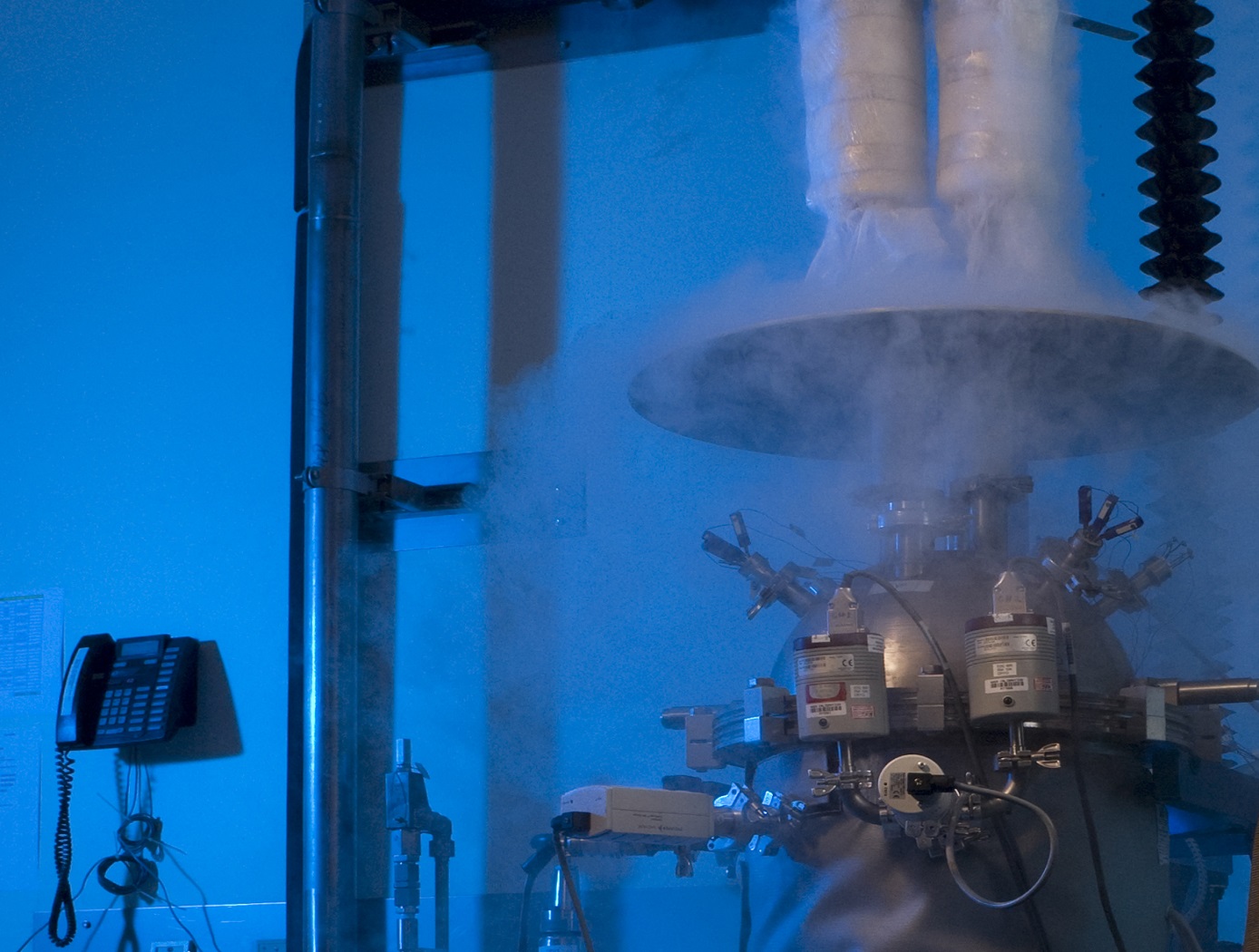
Cryostat-100
Cryostat-100 combines the best features of previous cryostats developed by NASA, while offering new features and conveniences. This unit can readily handle the full range of cryogenic-vacuum conditions over several orders of magnitude of heat flux. Guide rings, handling tools, and other design items make insulation change-out and test measurement verification highly reliable and efficient to operate. The new apparatus requires less ancillary equipment (it is not connected to storage tank, phase separator, subcooler, etc.) to operate properly. It is top-loading, which makes disassembly, change-out, and instrumentation hook-up much faster. The thermal stability is improved because of internal vapor plates, a single-tube system of filling and venting, bellows feed-throughs, Kevlar thread suspensions, and heavy-wall stainless-steel construction.
The cold mass of Cryostat-100 is 1m long, with a diameter of 168 mm. The test articles can therefore be of a corresponding length and diameter, with a nominal thickness of 25.4 mm. Shorter lengths are acceptable, and thicknesses may be from 0 mm to 50 mm. Tests are conducted from ambient pressure (760 torr) to high vacuum (below 110-4 torr) and at any vacuum pressure increment between these two extremes. The residual gas (and purge gas) is typically nitrogen but can be any purge gas, such as helium, argon, or carbon dioxide.
Typically, eight cold vacuum pressures are performed for each test series. The warm boundary temperature is approximately 293 K, and the cold boundary temperature is approximately 78 K. The delta temperature for the cryogenic testing is therefore approximately 215 K. A unique lift mechanism provides for change-out of the insulation test specimens. It also provides for maintenance and other operations in the most effective and time-efficient ways. The lift mechanism is also a key to the modularity of the overall system.
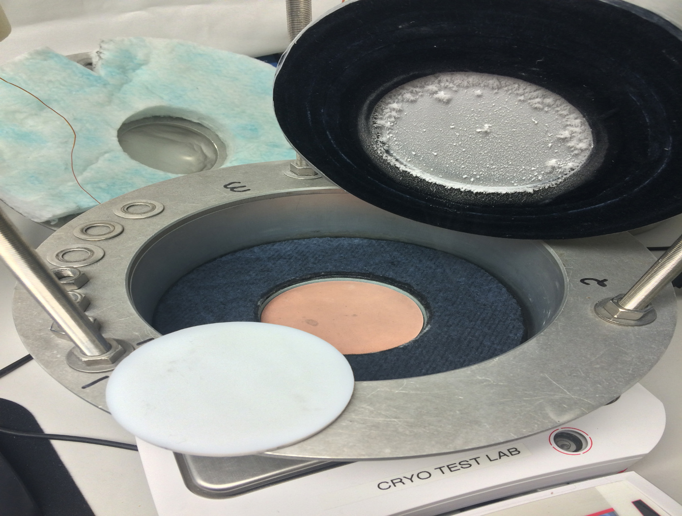
Macroflash (Cup Cryostat)
Advances in new polymers and composites along with growing industrial needs in below-ambient temperature applications have brought about the Macroflash development. Accurate thermal performance information, including effective thermal conductivity data, are needed under relevant end-use conditions. The Macroflash is a practical tool for basic testing of common materials or research evaluation of advanced materials/systems.
The Macroflash can test solids, foams, or powders that are homogeneous or layered in composition. Test specimens are typically 75mm in diameter and 6mm in thickness. The cold side is maintained by liquid nitrogen at 77 K while a heater disk maintains a steady warm-side temperature from ambient up to 373 K. The steady boiloff of the liquid nitrogen provides a direct measure of the heat energy transferred through the thickness of the test specimen. Nitrogen or other gas is supplied to the instrument to establish a stable, moisture-free, ambient pressure environment. Different compression loading levels can also be conveniently applied to the test specimen as needed for accurate, field-representative thermal performance data. The Macroflash is calibrated from approximately 10 mW/m-K to 800 mW/m-K using well-characterized materials.

Data Transfer for Multiple Sensor Networks
High-temperature sensors have been used in silicon carbide electronic oscillator circuits. The frequency of the oscillator changes as a function of changes in the sensor's parameters, such as pressure. This change is analogous to changes in the pitch of a person's voice. The output of this oscillator, and many others may be superimposed onto a single medium. This medium may be the power lines supplying current to the sensors, a third wire dedicated to data transmission, the airwaves through radio transmission, or an optical or other medium. However, with nothing to distinguish the identities of each source, this system is useless. Using frequency dividers and linear feedback shift registers, comprised of flip flops and combinatorial logic gates connected to each oscillator, unique bit stream codes may be generated. These unique codes are used to amplitude modulate the output of the sensor (both amplitude shift keying and on-off keying are applicable). By using a dividend of the oscillator frequency to generate the code, a constant a priori number of oscillator cycles will define each bit. At the receiver, a detected frequency will have associated with it a stored code pattern. Thus, a detected frequency will have a unique modulation pattern or "voice," disassociating it from noise and from other transmitting sensors. These codes may be pseudorandom binary sequences (PRBS), ASCII characters, gold codes, etc. The detected code length and frequency are measured, offering intelligent data transfer.
This is an early-stage technology requiring additional development. Glenn welcomes co-development opportunities.
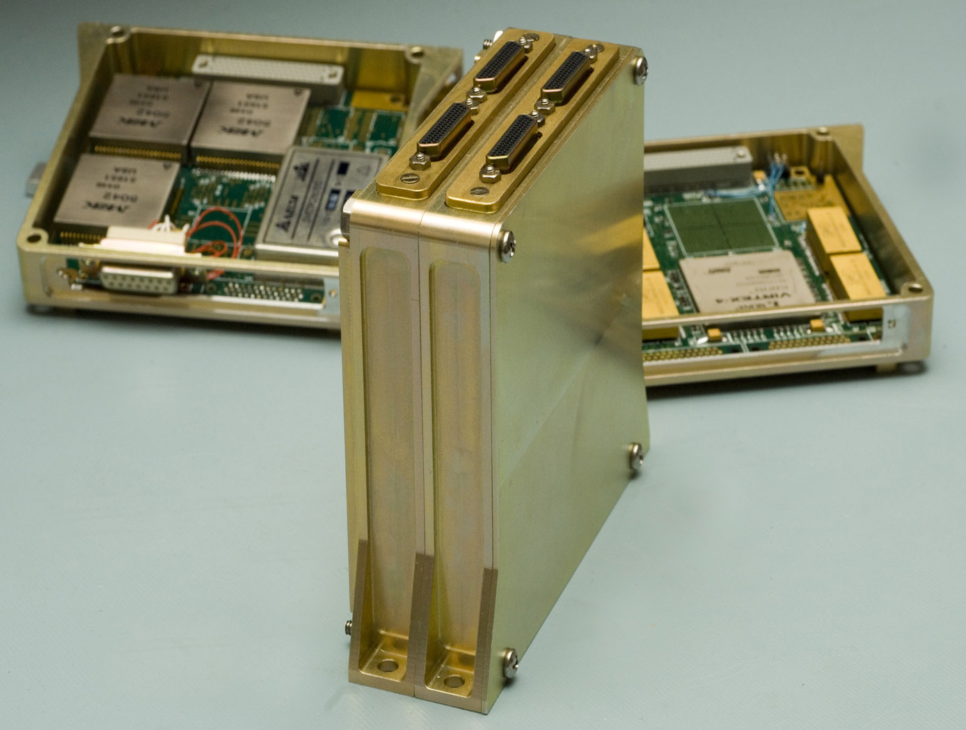
SpaceCube v2.0 Processor with DDR2 Memory Upgrade
This new version of the card assembly will feature a total of eight 4x DDR2 SDRAM memories per Xilinx FPGA. A dedicated regulator was included to compensate for the lower operating voltage of DDR2 in comparison to the older DDR memory. The DDR2 memories are grouped in pairs with shared address/command/control lines. By sharing those lines, the number of Xilinx I/Os for the DDR2 interfaces could be reduced. These improvements extend the life and design of the processor and provide even greater memory throughput to support the next generation of instruments.
A Broadband, Compact Low-Power microwave Radiometer Down Converter for Small Satellite Applications
The system includes a fundamental local oscillator (LO) source composed of a broad-band tunable frequency synthesizer as well as a crystal oscillator. The synthesizer employs a harmonic doubler to expand frequency coverage. The CubeRRT system uses a series of RF switches and band-pass filters, to select the desired harmonic while suppressing unwanted harmonics. The CubeRRT system uniquely combines several technologies to minimize the number of frequency banks and thus reduce mass, volume and power requirements. The CubeRRT system uses four frequency banks in order to provide continuous microwave receiver coverage from 6GHz to 40GHz.

RFID-Enabled Wireless Instrumentation
With a form factor close to a deck of playing cards, the system interrogator has custom software to interface with and service a population of sensor tags at the required data rates. Each EPCglobal C1G2 sensor tag uses incident interrogator energy to charge its small integrated circuit (IC), which reads an internal memory bank, encodes identification data, and uses that information to modulate and backscatter a reply to the interrogator using reflected interrogator energy. Two tag interfaces allow the attached processor to power the reading/writing of data to the tag memory and then allows the interrogator to power the reading of the tag memory data. When neither of the two interfaces are engaged, the RFID IC is completely powered down. Reading and writing tag memory consumes relatively little power compared to the power draw of active transmitter/receiver protocols like Bluetooth, Zigbee, and Wi-Fi. Compared to passive sensing protocols, this wireless instrumentation system enables sampling of a larger population of tags without the computational burden associated with surface acoustic wave (SAW) sensing. RFID-Enabled Wireless Instrumentation technology allows the RFID interrogator to write data through the interface of a sensor tag memory bank using only interrogator power. With only minimal cost to the sensors power budget, the microcontroller unit can read that data out over the serial interface. The sensor can transmit and receive data at no effective cost to its small coin cell battery power supply.
This technology is readiness level (TRL) 8 (actual system completed and "flight qualified" through test and demonstration) and the innovation is now available for your company to license. Please note that NASA does not manufacture products itself for commercial sale.

Multi-Parameter Aerosol Scattering Sensor
Originally developed to demonstrate a highly accurate, low-false-alarm, early fire detection system in space, this advanced technology level system utilizes a durable, low-cost, compact laser source and detector array, similar to CD/DVD player technology, to analyze the interaction of light with particles. The smart system is ideal for detecting a diverse range of particles found in pollution, emissions, fire and other atmospheric toxins while introducing a flexibility that enables its use in multiple environments, especially when coupled with UAVs or other remote platforms.
The MPASS contains a number of features that allow users to make the most of its pioneering capabilities. The self-contained system is lightweight and has been miniaturized and packaged to easily fit into the palm of your hand. A USB port enables the system to be powered, configured, and accessed through its onboard central processing unit. The advanced graphical user interface, custom software, and optimized algorithm allows the user to select known properties when applicable, and to program the system for maximum performance. The dashboard also provides visual feedback through graphical displays, making it easy to analyze the data and make real-time decisions. The system is designed with Bluetooth expansion capability, adding flexibility and communication through potential custom cellular phone applications. Once programmed, the battery-powered wireless sensor system opens the door to monitoring remote areas and extreme environments never thought possible.
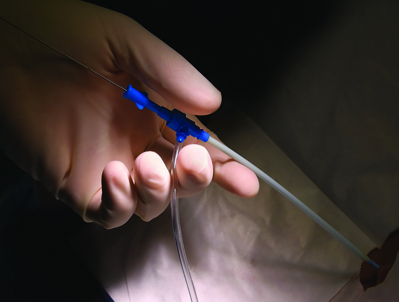
Highly Accurate Position Detection and Shape Sensing with Fiber Optics
NASA's novel method was developed to more accurately measure the position and shape of optical fibers. Multi-core optical fibers contain multiple light-guiding cores arranged symmetrically. Sensors, such as FBGs, are embedded into each of the cores (Figure 1). Such an arrangement allows for the measurement of strain in each core of the fiber at specific axial locations along the fiber. When a multi-core fiber is subjected to bending, the strain imposed in each core relative to one another is used to provide position information (Figure 2).
In the past, shape-sensing measurements using optical fibers estimated bending at sequential points along the fiber, and the resulting measurement had many discontinuities and errors. The combination of these errors resulted in a very poor indication of actual fiber position in three-dimensional space. NASA's patent-pending algorithms and apparatus incorporate not only fiber bending measurements, but fiber twisting measurements as well, to eliminate previous sources of error. The uniqueness of the algorithm is in how the curvature, bend-direction, and twisting information of the fiber are all brought together to obtain a highly accurate 3-D location and shape characterization. The new methods have been demonstrated to significantly improve the accuracy of multi-core fiber optic shape sensors.
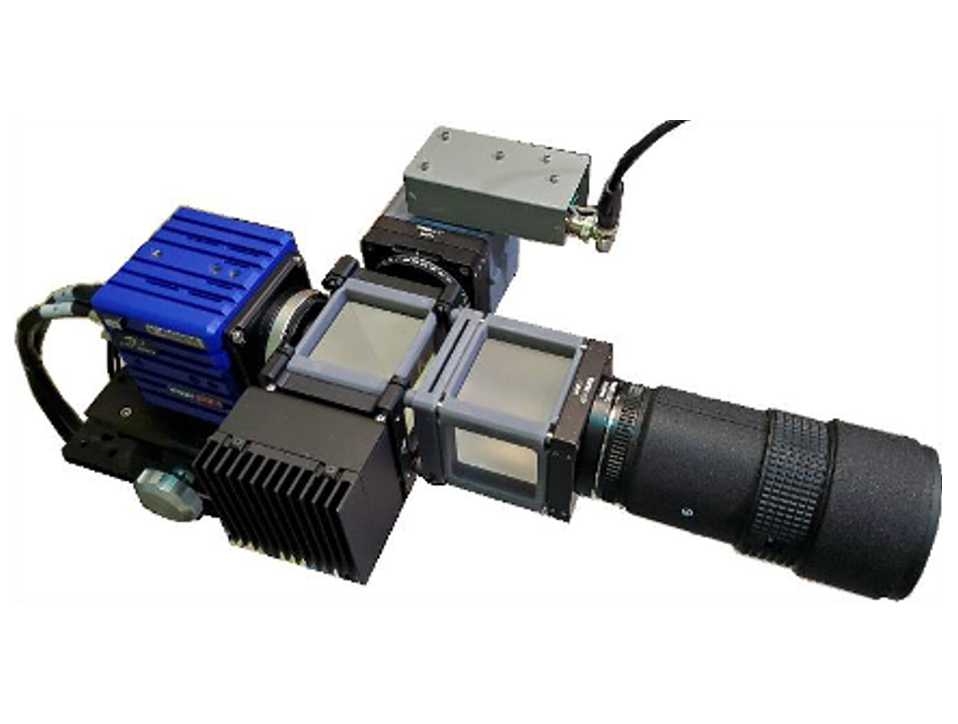
Assembly for Simplified Hi-Res Flow Visualization
NASAs single grid, self-aligned focusing schlieren optical assembly is attached to a commercial-off-the-shelf camera. It directs light from the light source through a condenser lens and linear polarizer towards a polarizing beam-splitter where the linear, vertically-polarized component of light is reflected onto the optical axis of the instrument. The light passes through a Ronchi ruling grid, a polarizing prism, and a quarter-wave plate prior to projection from the assembly as right-circularly polarized light. The grid-patterned light (having passed through the Ronchi grid) is directed past the density object onto a retroreflective background that serves as the source grid. Upon reflection off the retroreflective background, the polarization state of light is mirrored. It passes the density object a second time and is then reimaged by the system. Upon encountering the polarizing prism the second time, the light is refracted resulting in a slight offset. This refracted light passes through the Ronchi ruling grid, now serving as the cutoff grid, for a second time before being imaged by the camera.
Both small- and large-scale experimental set ups have been evaluated and shown to be capable of fields-of-view of 10 and 300 millimeters respectively. Observed depths of field were found to be comparable to existing systems. Light sources, polarizing prisms, retroreflective materials and lenses can be customized to suit a particular experiment. For example, with a high speed camera and laser light source, the system has collected flow images at a rate of 1MHz.
View more patents

