Search
Optics

Multi-Edge Slant Target for Non-Localized MTF Measurement
NASA’s Multi-Edge Slant Target is a precision-manufactured 1-inch diameter chrome-on-quartz calibration plate featuring a sophisticated geometric pattern optimized for comprehensive MTF analysis. The repeated slant edges allow for MTF to be directly sampled across the sensor in discrete locations, as opposed to solely in the center along a single edge of the image. Once the target plate is imaged, the image files can be used to calculate MTF measurements using standard methods as outlined in ISO 12233. The MTF data can then be visualized as a heatmap, which illustrates image quality of the imaging system as a function of discretely localized optical aberrations or spatial non-uniformities in the system’s electro-optical assembly.
Fabricated using advanced laser lithography techniques with sub-micron precision, NASA’s target provides exceptional contrast ratios meeting ISO 12233 standards. The chrome coating creates sharp, high-contrast edges on a clear quartz substrate, enabling backlit operation with blackbody or integrating sphere sources across broad spectral ranges. The target's unique geometric design includes positioning markers for precise alignment and multiple sampling regions that enable enhanced MTF measurement accuracy.
NASA’s Multi-Edge MTF Slant Target can be used in any application requiring characterization of 2D imaging systems from UV-VIS to MWIR. Firms that develop multi-spectral, hyper-spectral, thermal, and visible light imaging systems may benefit from the full-field spatial performance characterization it enables. Slant targets manufacturers may be interested in adding this capability to their product lines. The invention has been fabricated and validated (it is frequently used by NASA’s SCIFLI team), and is available for patent licensing.
Sensors

Wide Field Receiver Calibration Device for Micro Pulse LiDAR
Below an MPL’s minimum overlap range, the return signals are not completely in the instrument’s field of view, so the receiver only captures a portion of the backscatter laser pulse. MPL overlap ranges vary, but is usually between 4-8 km, encompassing the lower atmosphere where most aerosols reside. Commonly, correction entails recording horizontal profiles that require a ~10 km clear line-of-sight and homogenous atmospheric conditions, limiting the solution’s practicality.
In contrast, NASA’s WFR device corrects for the overlap using a second receiver co-aligned with the MPL that captures the same backscattered laser pulses as the MPL receiver, but with a ~20x wider FOV that enables a much shorter overlap range from ~6 km down to 250 m. Thus, the combination of the WFR and MPL can capture accurate signals from near surface to the stratosphere. The WFR utilizes the same detector as the MPL, enabling it to connect to the MPL data system for synced data acquisition. By eliminating the need for homogeneous horizontal measurements to determine the MPL overlap function, overlap corrections are more easily and more frequently obtained. Further, the WFR mount base was designed to easily integrate with MPLs.
NASA originally developed this device to improve accuracy of MPLs in the MPLNET, ensuring data collected are both accurate and reliable, thereby enhancing our understanding of atmospheric processes and contributing to more informed climate research and environmental modeling. The technology’s operational ease, flexibility, and cost savings are relevant to a wide range of scientific, environmental, and industrial applications. Companies that manufacture and sell MPLs may wish to offer this advanced calibration device as a product to enhance accuracy of MPL-based measurements. This NASA technology is at TRL 8 (Actual system completed and "flight qualified" through test and demonstration.) and is available for patent licensing.
manufacturing
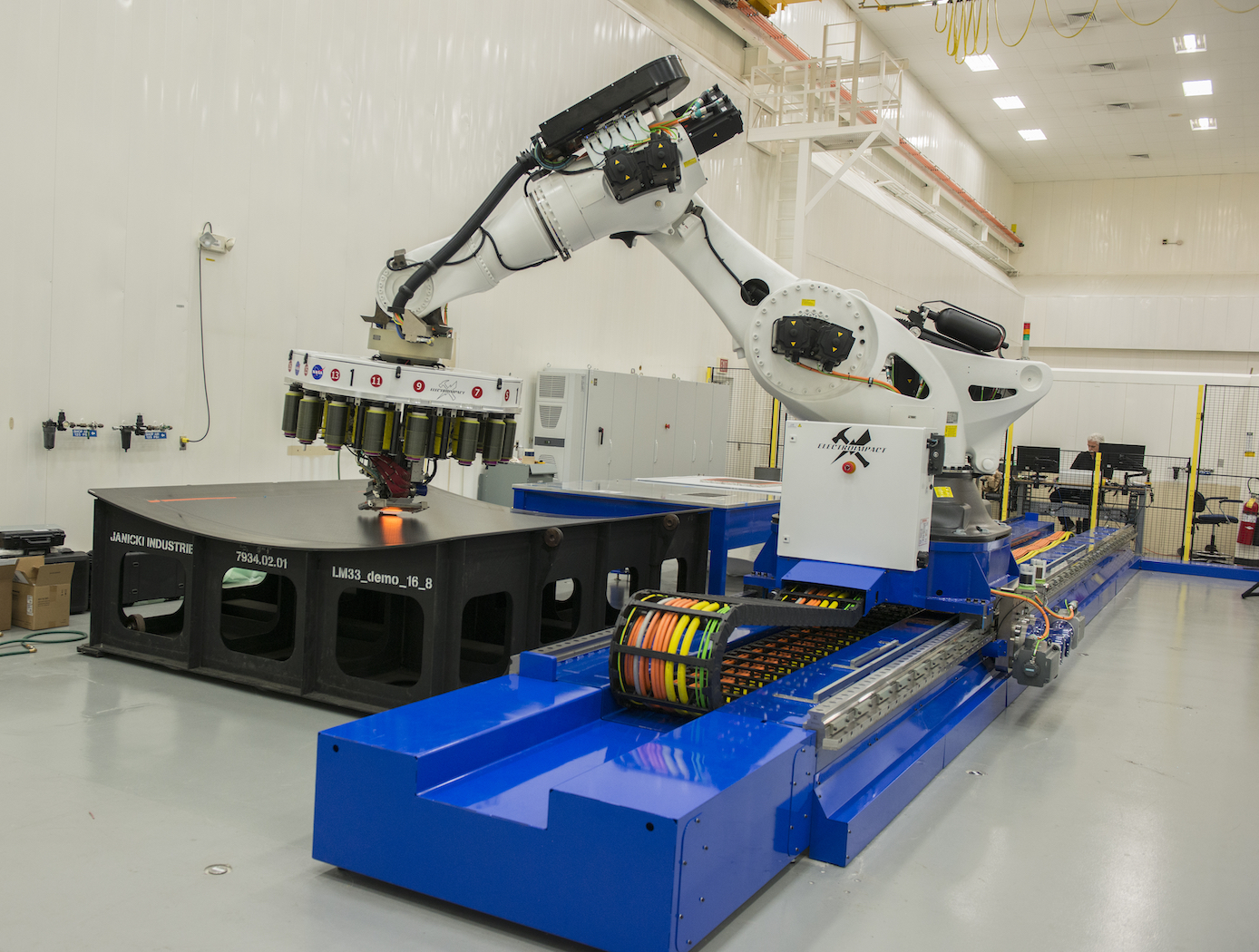
Calibration System for Automated Fiber Placement
NASA's new calibration system is a proprietary method to quickly design and make predictable and repeatable gap-and-overlap defects when employing AFP. The system creates defects within the course of layup with known sizes, geometries, and locations. Using this defect-creation technique, one can now accurately quantify the ability to detect defects on inspection systems, perform accurate risk assessments, and calibrate in-situ inspection equipment to specific materials. The equipment that makes the defects can be efficiently and inexpensively 3D printed. This technique is currently being used to successfully calibrate NASA's in situ inspection system for their AFP equipment.
AFP is experiencing increasing adoption in aerospace, automotive, and other industries that leverage large-scale advanced composite components. NASA's new AFP calibration system could be very useful to companies that develop and manufacture AFP machines or AFP machine inspection equipment to improve the quality of their products in a provable manner. Furthermore, users of AFP machines may find value in the tool for creating their own calibration standards.
Sensors

Self-Calibrating Virtual Sensor
The virtual air data sensor leverages smartphone-grade inertial and GPS sensors with advanced computational methods to generate accurate air flow data in real time. The innovation uses inexpensive sensors typically present on smartphones, along with real-time modeling, filtering, and data reconstruction using kinematic equations. Operating within the aircraft fuselage, the algorithm avoids environmental exposure and flow field complications affecting traditional external sensors.
The algorithm employs a dual-methodology approach for real-time air flow estimation. It calibrates an aerodynamic model during calm air conditions, using aircraft response characteristics to compute air flow angles from vertical and lateral acceleration data through frequency-domain modeling. Simultaneously, kinematic relationships with GPS-corrected sensor bias estimation reconstruct independent air flow data at lower update rates. Advanced complementary filtering blends these streams to generate continuous airspeed, angle of attack, and sideslip angle measurements. The algorithm incorporates automated calibration, vertical acceleration-based alpha estimation, and GPS-based low-frequency angle reconstruction using kinematic expressions.
The innovative algorithm is self-calibrating and provides independent, reliable, and accurate virtual sensing that can be implemented with readily-available hardware. The technology is currently TRL 5 (component validated in relevant environment) and available for licensing.

