Search
communications

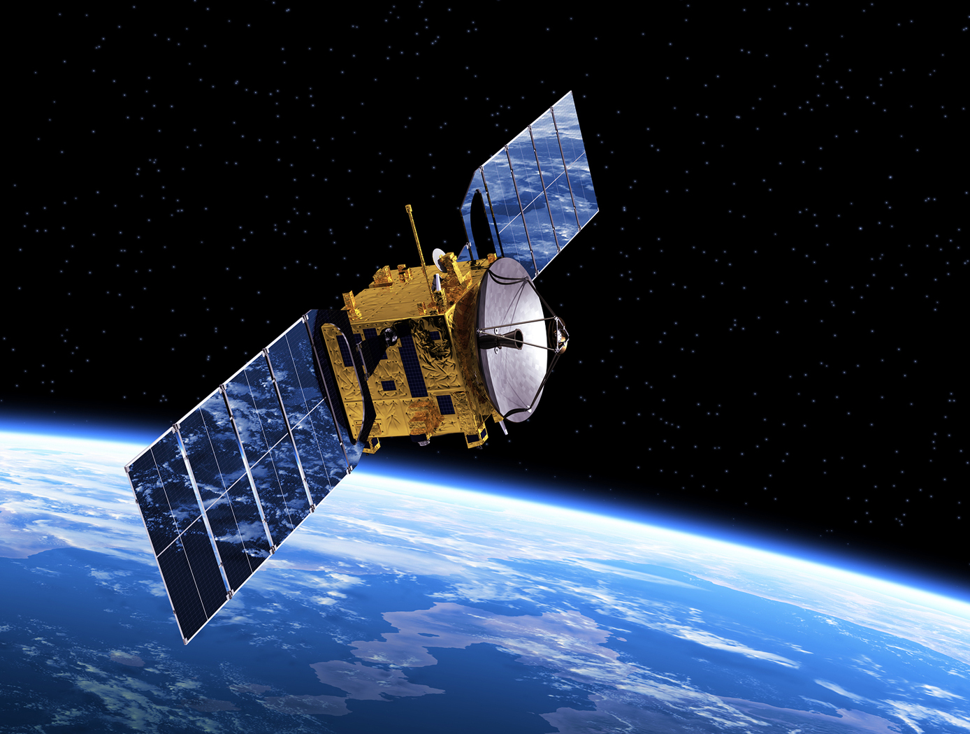
Space Optical Communications Using Laser Beams
This invention provides a new method for optical data transmissions from satellites using laser arrays for laser beam pointing. The system is simple, static, compact, and provides accurate pointing, acquisition, and tracking (PAT). It combines a lens system and a vertical-cavity surface-emitting laser VCSEL)/Photodetector Array, both mature technologies, in a novel way for PAT. It can improve the PAT system's size, weight, and power (SWaP) in comparison to current systems. Preliminary analysis indicates that this system is applicable to transmissions between satellites in low-Earth orbit (LEO) and ground terminals. Computer simulations using this design have been made for the application of this innovation to a CubeSat in LEO. The computer simulations included modeling the laser source and diffraction effects due to wave optics. The pointing used a diffraction limited lens system and a VCSEL array. These capabilities make it possible to model laser beam propagation over long space communication distances. Laser beam pointing is very challenging for LEO, including science missions. Current architectures use dynamical systems, (i.e., moving parts, e.g., fast-steering mirrors (FSM), and/or gimbals) to turn the laser to point to the ground terminal, and some use vibration isolation platforms as well. This static system has the potential to replace the current dynamic systems and vibration isolation platforms, dependent on studies for the particular application. For these electro-optical systems, reaction times to pointing changes and vibrations are on the nanosecond time scale, much faster than those for mechanical systems. For LEO terminals, slew rates are not a concern with this new system.
Communications

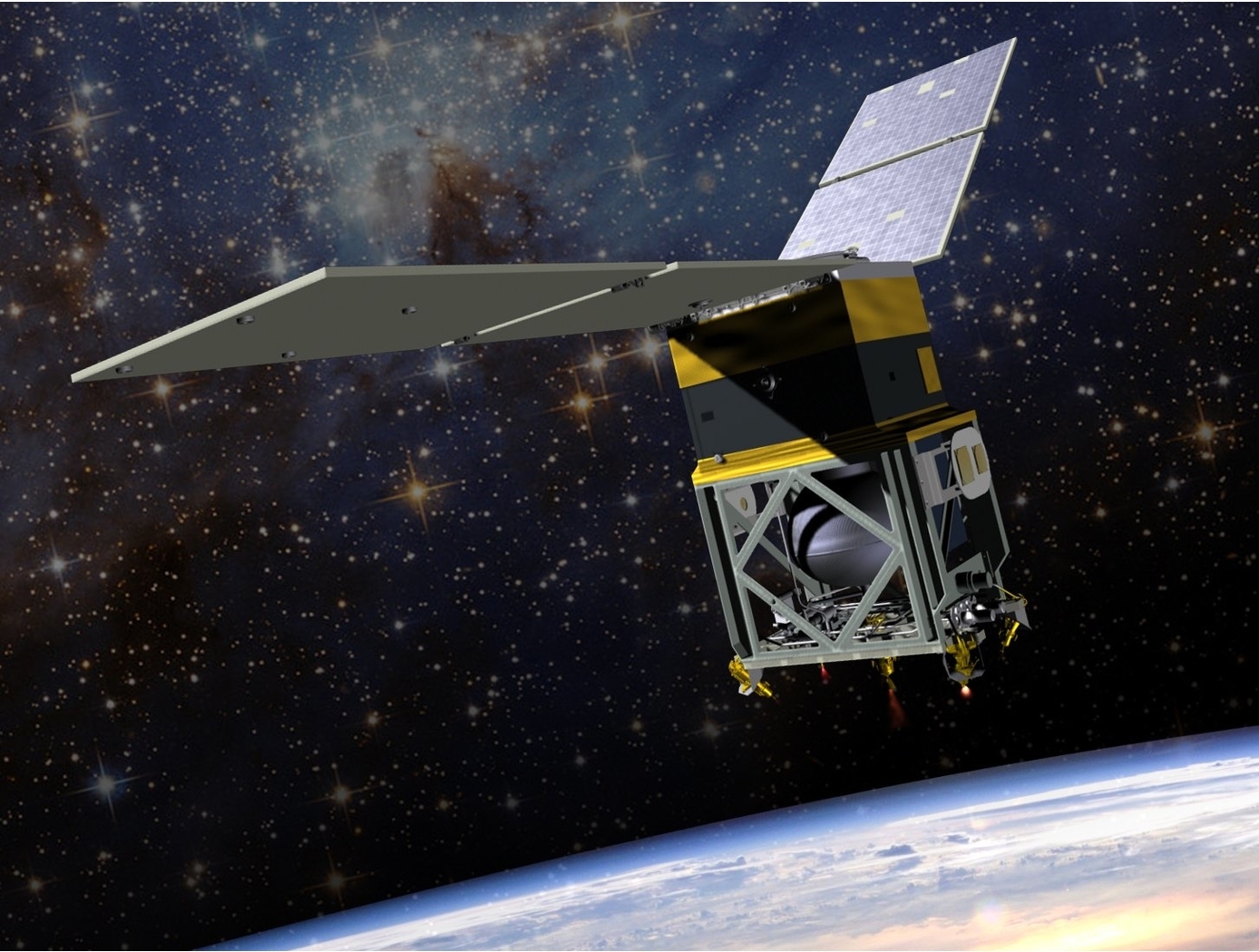
Lightweight, Self-Deployable Helical Antenna
NASA's newly developed antenna is lightweight (at or below 2 grams), low volume (at or below 1.2 cm3), and low stowage thickness (approx. 0.7 mm), all while delivering high performance (at or above 10 dBi gain). The antenna includes a novel design-material combination in a helical coil conformation. The design allows the antenna to compress for stowage (e.g., satellite launch), then self-deploy at the desired time in orbit.
NASA's lightweight, self-deployable helical antenna can be integrated into a thin-film solar array (or other large deployable structures). Integrating antenna elements into deployable structures such as power generation arrays allows spacecraft designers to maximize the inherently limited resources (e.g., mass, volume, surface area) available in a small spacecraft. When used as a standalone (i.e., single antenna) setup, the the invention offers moderate advantages in terms of stowage thickness, volume, and mass. However, in applications that require antenna arrays, these advantages become multiplicative, resulting in the system offering the same or higher data rate performance while possessing a significantly reduced form factor.
Prototypes of NASA's self-deployable, helical antenna have been fabricated in S-band, X-band, and Ka-band, all of which exhibited high performance. The antenna may find application in SmallSat communications (in deep space and LEO), as well as cases where low mass and stowage volume are valued and high antenna gain is required.


