Lightweight, Self-Deployable Helical Antenna
Communications
Lightweight, Self-Deployable Helical Antenna (MFS-TOPS-113)
High data rate communications in a small form factor
Overview
SmallSats are experiencing increasing adoption in the satellite industry. While initially used primarily for technology demonstrations in low Earth orbit (LEO), enhanced capabilities have enabled SmallSat use for a broad number of applications. Today, sending small spacecraft beyond LEO to Lunar or deep space environments is attracting both scientific and commercial interest. Such missions are mass and volume constrained, yet must provide high data rate communications. Historically, patch antennas have been used for SmallSat communications. While new antenna technologies are in development, some are not optimized for size, mass, and performance - especially beyond LEO.
Engineers at NASA's Marshall Space Flight Center identified the need for a small form factor antenna to provide high data rate communications for such missions. In response, they developed a self-deployable helical antenna that is lightweight, low volume, and has low stowage thickness while delivering high data rate performance.
The Technology
NASA's newly developed antenna is lightweight (at or below 2 grams), low volume (at or below 1.2 cm3), and low stowage thickness (approx. 0.7 mm), all while delivering high performance (at or above 10 dBi gain). The antenna includes a novel design-material combination in a helical coil conformation. The design allows the antenna to compress for stowage (e.g., satellite launch), then self-deploy at the desired time in orbit.
NASA's lightweight, self-deployable helical antenna can be integrated into a thin-film solar array (or other large deployable structures). Integrating antenna elements into deployable structures such as power generation arrays allows spacecraft designers to maximize the inherently limited resources (e.g., mass, volume, surface area) available in a small spacecraft. When used as a standalone (i.e., single antenna) setup, the the invention offers moderate advantages in terms of stowage thickness, volume, and mass. However, in applications that require antenna arrays, these advantages become multiplicative, resulting in the system offering the same or higher data rate performance while possessing a significantly reduced form factor.
Prototypes of NASA's self-deployable, helical antenna have been fabricated in S-band, X-band, and Ka-band, all of which exhibited high performance. The antenna may find application in SmallSat communications (in deep space and LEO), as well as cases where low mass and stowage volume are valued and high antenna gain is required.
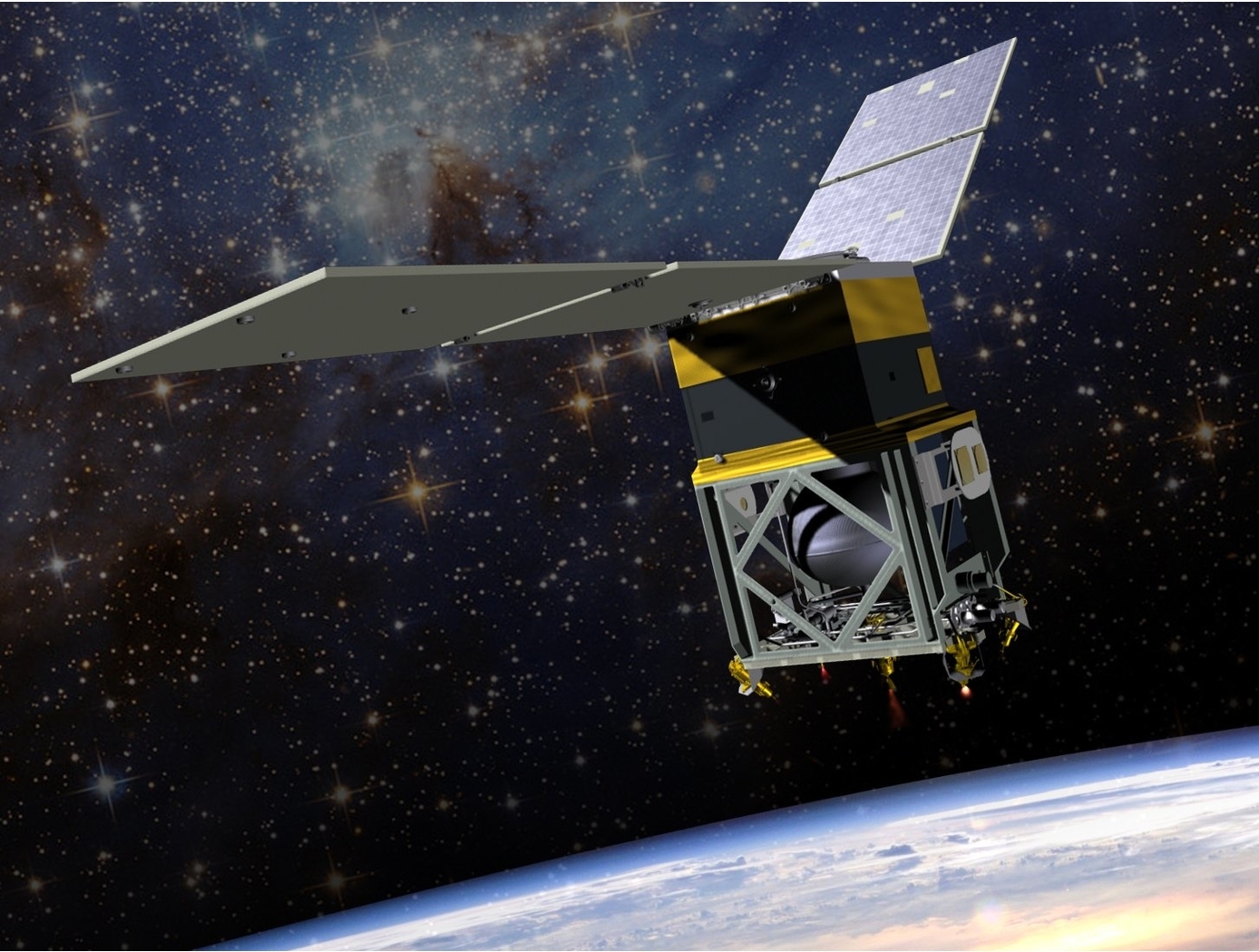
 - a launch stowed, orbit-deployed array on which thin-film photovoltaic and antenna elements are embedded.")
Benefits
- Form factor & design: NASA’s helical antenna stows with much less volume than conventional helical and patch antennas, self-deploys to designed specifications, and still retains the advantages inherent to helical antennas available on the market.
- Reduced mass: In addition to low volume, NASA's self-deployable helical antenna is lightweight - offering mass conservation while still providing high data rate communications.
- Useful in array applications: In array implementations (e.g., 16x16), the invention delivers comparable performance in a package one-tenth the size and mass of traditional antenna arrays. Furthermore, the invention can be integrated into existing deployable structures (e.g., power generation arrays).
Applications
- SmallSat communications: NASA's helical antenna provides high data rate communications in a deployable form factor suitable for SmallSats, as well as larger spacecraft. While the antenna (and arrays made thereof) may be particularly useful for deep space missions, it will likely also provide advantages to spacecraft in LEO.
- Military communications: Due to its low mass, low stowage volume, and high gain, NASA's helical antenna may be suitable for satellite-based military communications.
Technology Details
Communications
MFS-TOPS-113
MFS-34025-1
Patent Pending
|
Tags:
|
|
|
Related Links:
|
Similar Results

Multi-and Wide-Band Single-Feed Patch Antenna
NASA's patch antenna technology exhibits higher operational bandwidth (on the order of 20%) than typical patch antennas (less than 10%) and can operate across integer-multiple frequency bands (e.g. S/X, C/X, S/C). Testing of the antenna design has demonstrated > 6dB of gain on both S and X bands (boresight), with an axial ratio of < 6dB and voltage standing wave ratio (VSWR) < 3:1 throughout the entire near-Earth network (NEN) operating bands (22.4GHz and 88.4GHz) with hemispherical coverage. The patch size is on the order of 10 x 10 cm and with associated electronics, is about 1 cm in height.

SmallSat Standardized Architecture
SmallSat Standardized Architecture is architecture that is modularized, pressurizable, thermally controlled spacecraft-designed to host ruggedized commercial off-the-shelf (COTS) instrumentation in a terrestrial-like environment on orbit. The architecture takes advantage of a pressurizable volume for both spacecraft and payload systems. The pressurizable volume provides multiple benefits, primarily in thermal design. By maintaining one atmosphere of pressure inside the SmallSat, materials that might otherwise outgas and/or fail and/or cause significant contamination issues, are no longer a concern. This also means that certain vibration-absorbing materials/designs used in COTS hardware can be used on orbit. Additionally, printed circuit boards do not have to be redesigned for thermal requirements, plus conformal coating and contamination bake-outs are no longer required.
The SmallSat architecture is designed to take advantage of the United States Air Force (USAF) Rideshare Program and the Evolved Expendable Launch Vehicle Secondary Payload Adaptor (ESPA) ring. The ESPA ring comes in two sizes: standard and Grande. The architecture has two main configurations, one designed for the ESPA Grande, and the other for the standard ESPA ring. The ESPA Grande version is a hockey-puck-shaped spacecraft bus measuring approximately 40 inches in diameter and 20 inches in height. This version takes full advantage of the ESPA Grandes 300-kilogram capability per attachment point.

High Performance, All-Metal X-Band Patch Antenna
The patch antenna consists of two radiating metal patch elements, a metal feed circuit, choke rings, several alignment spacers, a SMA connector, and a mounting lid giving the antenna a total diameter of 54 mm; small enough to fit in a coffee cup. The signal is carried between the lower patch and the circuit via a coaxial transmission structure, in which the probes are the inner conductor and the antenna structure is the outer conductor. The patch antenna is constructed entirely of metal, offering rugged physical durability while delivering superior performance. This advanced material not only enables the antenna to handle higher power loads (exceeding 10 watts) but also ensures exceptional stability under demanding conditions—outperforming standard patch antennas made with traditional dielectric materials. It is also not susceptible to the manufacturing variability incurred from using dielectrics. Ideally, this metallic design also allows for reentry and reuse across missions.
The patch antenna is designed with integrated choke rings to effectively mitigate multipath signal interference, delivering an impressive front-to-back ratio of over 35 dB. Its integrated polarizer circuit enhances signal clarity and boosts overall efficiency, ensuring reliable communication in challenging environments. With support for both right- and left-handed circular polarization, the antenna achieves a co-polarization peak gain of 9 dBi and an axial ratio of less than 3 dB within a wide 50-degree orientation range. These advanced features provide superior signal performance and consistent clarity across diverse applications.
Although designed for space and planetary exploration applications, the antenna may also be valuable for terrestrial use cases with rugged conditions. The X-band patch antenna is at technology readiness level (TRL) 5 (component and/or breadboard validation in relevant environment) and is available for patent licensing.

Diminutive Assembly for Nanosatellite deploYables (DANY)
SmallSat designers seek to employ restraints and release mechanisms of minimal size and weight, often placing each on the outside of the SmallSat structure. Surprisingly, "fishing line" (released via burn through) is often used to secure and release deployables. Vibrations and forces generated during launch can stretch the fishing line, thus allowing these precious deployables to become damaged or otherwise not release properly later on. While these small sats are less expensive than their larger counterparts, satellite owners must minimize the chance that deployables are damaged or that deployment is unsuccessful.
Five years ago, engineers at NASA GSFC faced these SmallSat deployment challenges and knew a better way must exist to prevent equipment damage and ensure successful release. Investigating a host of designs to minimize size, weight, and cost while maximizing communication and mechanical reliability, NASA's engineers created DANY (the Diminutive Assembly for Nanosatellite deploYables). NASA's DANY technology uses spring-loaded metal pins, a reliable burn-through mechanism, efficient bracketing, and a circuit board - all within a 3.0" x 1.3" x 0.2" volume (smaller than a stack of 10 business cards) - to reliably stow and release deployables on command. Using DANY, stowed deployables are securely fastened using the spring-loaded locking pins. Upon receiving a deployment signal, a plastic restraining link is burned through which allows the spring-loaded pins to release the deployable and simultaneously trigger a switch to signal a successful deployment event.

Novel Antenna Concept for CubeSat Platforms
The side walls and railing rods of a CubeSat are replaced by RF radiators that double as supporting structures. The RF radiators are hollow railing rods with inner dimensions that function as a waveguide to carry RF energy at a desired frequency. Radiating slots are cut on two of the four sides of hollow tubes tube that are open to outside environment. Different operating frequency antennas may be placed at each of the Cubesats four corners. Thus the railing rods provide RF antenna functionality in addition to structurally supporting the CubeSat structure.
While this technology was designed for Cubesats, it may be utilized in any technology that utilizes a structural frame. The advantages of this system are increased reliability due to the elimination of deployment mechanisms and decreased payloads. Higher frequency
antennas with increased gain and directivity may be embedded into the rails. These higher frequencies are especially useful for remote sensing.

