Search
Mechanical and Fluid Systems

Low-Cost, Long-Lasting Valve Seal
NASA's technique simplifies the seat installation process by requiring less installation equipment, eliminating the need for unnecessary apparatus such as fasteners and retainers. Multiple seals can be installed simultaneously, saving both time and money.
NASA has tested the long-term performance of a solenoid actuated valve with a seat that was fitted using the new installation technique. The valve was fabricated and tested to determine high-cycle and internal leakage performance for an inductive pulsed plasma thruster (IPPT) application for in-space propulsion. The valve demonstrated the capability to throttle the gas flow rate while maintaining low leakage rates of less than
10<sup>-3</sup> standard cubic centimeters per second (sccss) of helium (He) at the beginning of the valves lifetime. The IPPT solenoid actuated valve test successfully reached 1 million cycles with desirable leakage performance, which is beyond traditional solenoid valve applications requirements. Future design iterations can further enhance the valve's life span and performance.
The seat seal installation method is most applicable to small valve instruments that have a small orifice of 0.5 inches or less.
Mechanical and Fluid Systems

Ball Valve Assembly Yields Linear Flowrate Control
Prototype thermal control valves for the next generation spacesuit were challenged in maintaining precise thermal control, so engineers created a design that functions like a traditional ball valve but added tapered-valley contours to the ball that yields a variable orifice which is more predictable at controlling flow.
The key differences between the TCBV and traditional v-channel ball valves are that this technology has one inlet and two outlets allowing the split-flow of fluids whereas traditional v-channel valves only have one inlet and one outlet. Additionally, traditional v-channel ball valves don’t enable the full flow rate of a given system while this technology does.
The ball valve is held in place within the TCBV using two PTFE seats compressed by spring-loaded side plates. The hole in the middle of the ball valve and adjoining tapered valleys mate with the PTFE seats to create varying sized orifices depending on valve position. Specially designed O-ring seals surrounding the ball valve assembly allow the seats to move within the pocket while preventing internal leakage.
In this technology’s spacesuit application, coolant is fed to the ported ball valve where the coolant is apportioned to each valve housing exit either primarily feeding the cooling and ventilation garment or the bypass circuit back to the spacesuit’s thermal cooling system. The apportionment is determined by the astronaut’s manual valve adjustment or automatically by the suit.
Mechanical and Fluid Systems
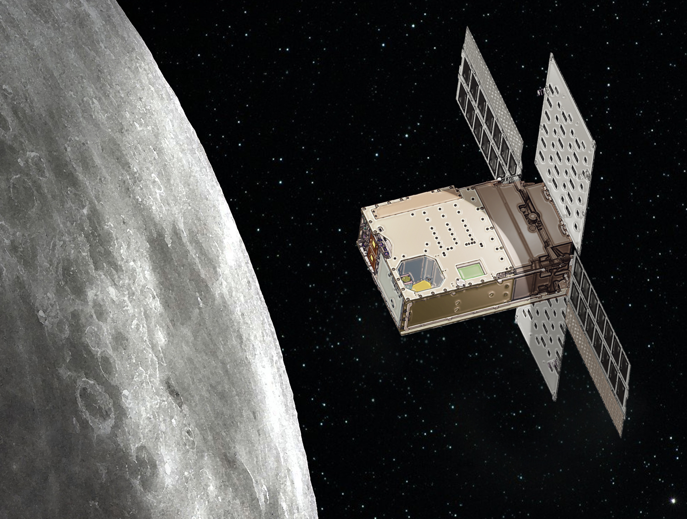
Miniature Separable Fill & Drain Valve
The Miniature Separable Fill & Drain Valve consists of two halves (ground and flight). The flight half is attached to the vehicle (i.e., CubeSat), and the ground half can be inserted into the vehicle in the same port as the flight half, connecting the two halves together. In normal state, the flight half seals the flow path. When the ground half is connected, the flow path is opened, allowing connected ground support equipment to supply fluid through the valve. The valve is manually operated.
There are redundant seals to eliminate leakage around the valve, including NASA's previously-patented Low-Cost, Long Lasting Valve Seal design (Patent No. 10,197,165; see MFS-TOPS-71 in the <i>Links</i> section of this flyer for more information) on the flight half. This eliminates the need for a swaged assembly process and the additional hardware and equipment that are typically required in conventional, elastomeric valve seat installations. The design also includes a cap for the flight half to ensure there is no leakage in flight configuration.
The Miniature Separable Fill & Drain Valve has been prototyped and provides valuable benefits for CubeSat applications. The valve could also have applications in the industrial processing industry where low flow devices are commonly used. The design is also scalable to larger applications where the removal of the actuation device would be desired.
Mechanical and Fluid Systems
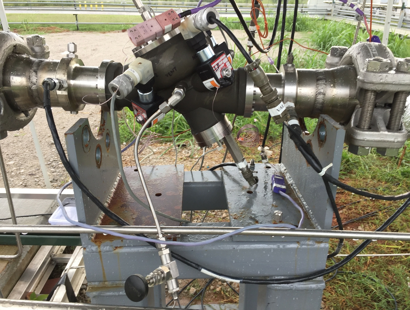
Cryogenic Hydraulically Actuated Isolation Valve
NASA's cryogenic isolation valve technology uses solenoid valves powered by direct current (DC) electrical energy to control and redirect the energy stored in the upstream line pressure. Powering the solenoid valves only requires a DC power source capable of supplying 22 watts that can be distributed and controlled in an on/off manner. By achieving actuation using only upstream line pressure and a 22-watt DC power source, many additional support systems that are required for electromechanical and pneumatic actuation are eliminated. This reduction of parts results in several benefits, including reduced footprint, weight, and potential cost of the valve in addition to lower energy consumption.
NASA fabricated several operational prototype valves using this technology for a rocket company. The table below shows the results of tests performed on these valves under cryogenic conditions. Please contact the NASA MSFC Technology Transfer Office for additional information.
Mechanical and Fluid Systems
Debris-Tolerant Valve
NASA's Debris-Tolerant Valve is designed for use in machines/environments with a large quantity of airborne dust or other contaminants. Valves subjected to airborne contaminants tend to have limited lifetime due to damaged seals, bearings, and other internal components. The Debris-Tolerant Valve design addresses this problem with four core improvements over existing commercial valves that are typically used in dusty or debris-laden processes: (1) a new cylinder design that substantially decreases dust collection within the valve; (2) a rotational valve design that minimizes grinding and packing experienced by the standard ball valve; (3) the use of elastomeric seals rather than the Teflon-based seals used in existing valves which are prone to scratching and subsequent leakage; and (4) a bleed port for fluid intake that allows pressure to build slowly in the valve and eliminates the stirring of dust commonly caused by rapid inflow of air in existing valves.
The operational lifetime of NASA's Debris-Tolerant Valve exceeds the lifetime of a standard commercial valve and the existing selector valve used on the ISS by 12X and 6X, respectively. NASA's valve design has fewer parts than existing valves and could be disassembled without tools, enabling easier servicing and maintenance. The Debris-Tolerant Valve is only about one-seventh (1/7) the cost of the existing ISS selector valve.
Mechanical and Fluid Systems
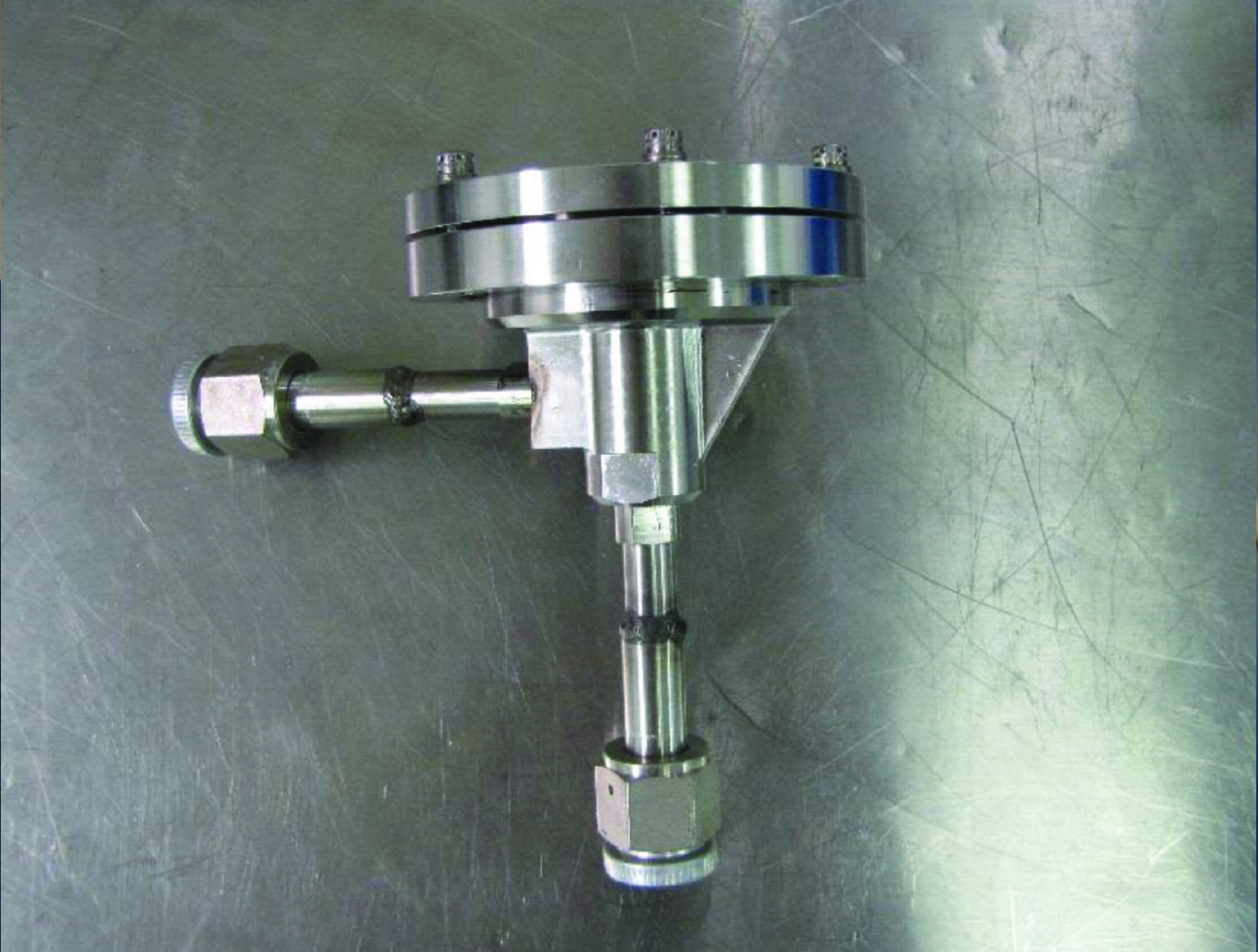
Pilot Assisted Check Valve for Low Pressure Applications
Check valves are traditionally designed as a simple poppet/spring system where the spring is designed to equal the force created from the sealing area of the valve seat multiplied by the cracking pressure. Since the valve seat diameter in these types of valves are relatively small, less than 0.5 inches diameter, a low cracking pressure required for back pressure relief devices results in a low spring preload. When sealing in the reverse direction, the typical 20 psid storage pressure of the cryogenic fluid is not enough pressure force to provide adequate sealing stress. To better control the cracking pressure and sealing force, a bellows mechanism was added to a poppet check valve (see Figure 2). The bellows serves as a reference pressure gauge; once the targeted pressure differential is reached, the bellows compresses and snaps the valve open. Prior to reaching the desired crack pressure differential, the bellows diaphragm is fully expanded, providing sufficient seal forces to prevent valve flow (including reverse flow) and undesired internal leakage. Room temperature testing of cracking pressure, full flow pressure, and flow capacity all showed improvements. The overall results of the test proved to be 10-20 times greater than conventional check valves with no internal leakage at three different pressure differentials.
Aerospace

Hypergol Refueling Tool (HRT) and Quick Disconnect (QD) System
The HRT and QD System was designed for satellite Fill and Drain Valves (FDVs), however, the architecture and approach are extensible to all space assets that could potentially be fueled/re-fueled on and off the ground, including but not limited to manned crew vehicles, planetary rovers, and space habitats. In the same vein, the solution is extensible to spacecraft propellants, pressurants, and other media beyond hypergolic fuels. It can be used in the delivery or receipt of media.
The HRT-QD is a separate end adapter onto the HRT; the HRT-QD interfaces with the client FDV. The HRT utilizes two rotary drives to actuate the HRT-QD such that the HRT-QD can affect a seal to the FDV, and open/close the FDV while maintaining this seal. The HRT also has linear drive actuated mechanisms that locks/releases the HRT-QD from the HRT. The HRT is mated to a flexible fuel hose. The fuel hose allows propellant to be transferred from the servicer propellant transfer assembly into the HRT, and further into the HRT-QD and into the client spacecraft via the FDV. This system is mated to, and actuated, by Advanced Tool Drive System 2.0. This technology is TRL 4 (component and/or breadboard validated in laboratory environment) and available for licensing.
Propulsion

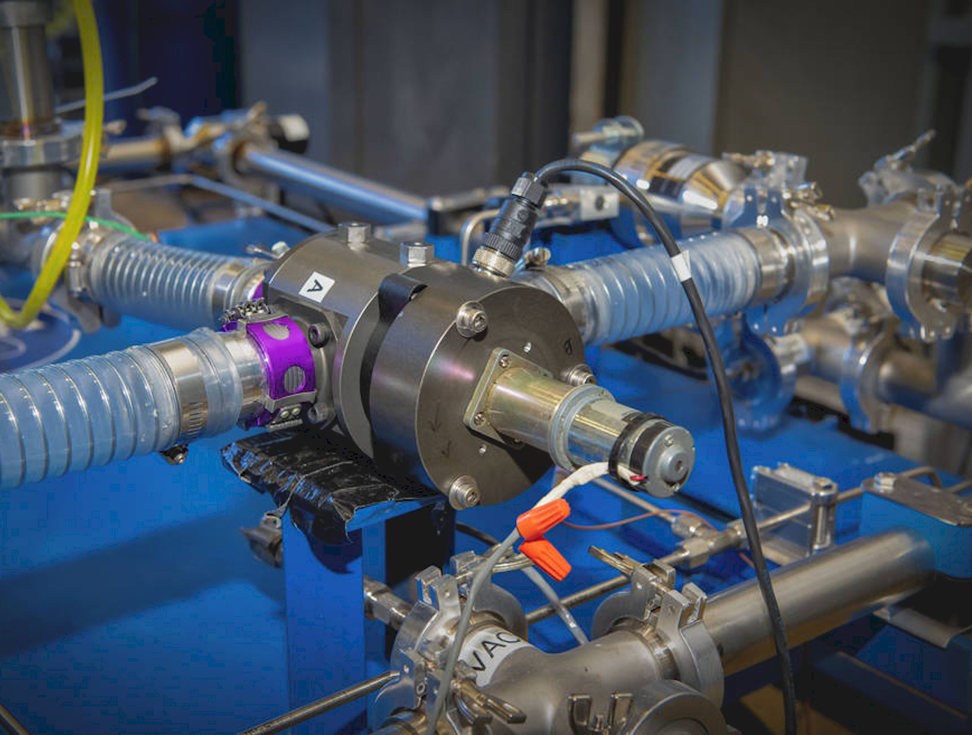
Fast-Acting, Deep-Throttling Hybrid Motor
Hybrid chemical motors offer an alternative to traditional liquid or solid motors for spacecraft, missiles, rockets, or other vehicles. The key advantage of a hybrid motor is the capability to throttle the motor via active control, which cannot be done in solid propellant motors. However, rapid throttling presents significant challenges to implement in practice.
Here, NASA has combined a deep-throttling hybrid motor previously developed by Utah State University with a fast-acting digital valve design to produce a fast-acting, deep-throttling hybrid. Testing performed to-date using a prototype of the hybrid motor and digital valve design has shown the new hybrid motor to be capable of full-scale throttling twice as fast (1 second throttling compared to 2 seconds) as previous control valve designs. With optimization, there is potential full-range throttling may be further reduced to 0.5 second, a 4x improvement over previous control valve designs for hybrid motors. Additionally, smaller mid-range thrust changes have currently been measured in the <0.5 second range.
With the throttling capability enabled by the implemented digital valves, it also becomes feasible to achieve thrust ratios of >40:1 for relatively small motors (<1000 N), opening up the opportunity to replace both the main propulsion system (MPS) and reaction control system (RCS) with a single, more efficient motor capable of meeting the needs of both on a spacecraft.
The hybrid motor is at technology readiness level (TRL) 4 (component and/or breadboard validation in laboratory environment) and is available for patent licensing.
Mechanical and Fluid Systems
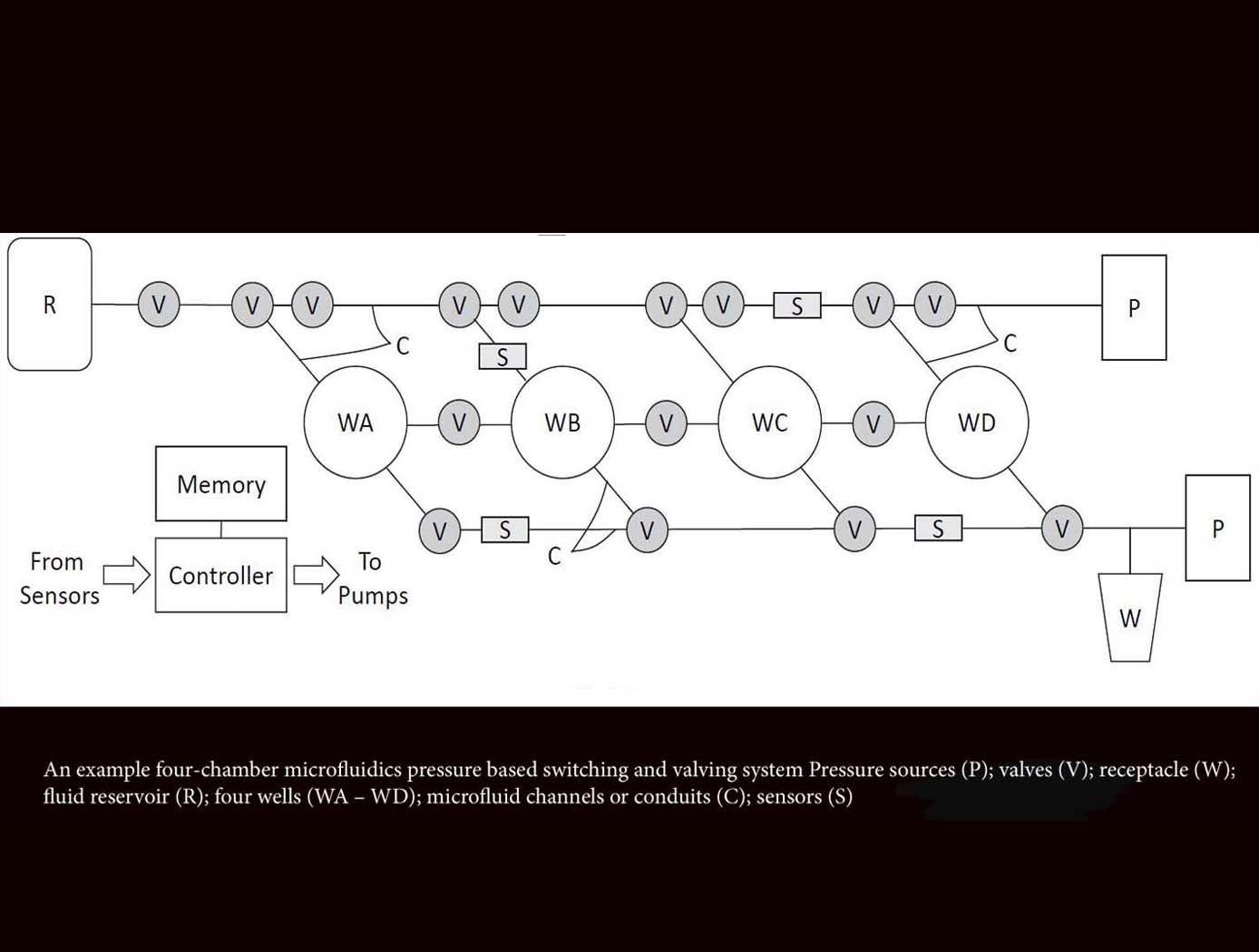
Microfluidics Pressure-Based Switching and Valving Array
The innovative technology from Ames acts as a microfluidics switch array, using combinations of pressure and flow conditions to achieve specific logic states that determine the sequences of sample movement between microfluidic wells. This advancement will enable automation of complex laboratory techniques not possible with earlier microfluidics technologies that are designed to follow predetermined flow paths and well targets. This novel method also enables autonomous operations including changing the flow paths and targeting well configurations in situ based on measured data decision parameters. This microfluidic system can be reconfigured for use in various experimental applications, requiring only an adjustment of the programmed pressure sequencing, reducing the need for custom design and development for each new application. For example, this technology could provide the ability to selectively constrain or move biological specimens in the experimental wells, allowing evolutionary studies of model organisms in response to various stressors, evaluation of different growth conditions on biological production of antibodies or other small molecule therapeutics, among other potential applications. Likewise, this platform can be used to foster time-dependent, step-wise, chemical reactions, which could be used for novel chemical processes or in situ resource utilization.

