Miniature Separable Fill & Drain Valve
Mechanical and Fluid Systems
Miniature Separable Fill & Drain Valve (MFS-TOPS-122)
A Manually Operated, Two-Part Valve Design
Overview
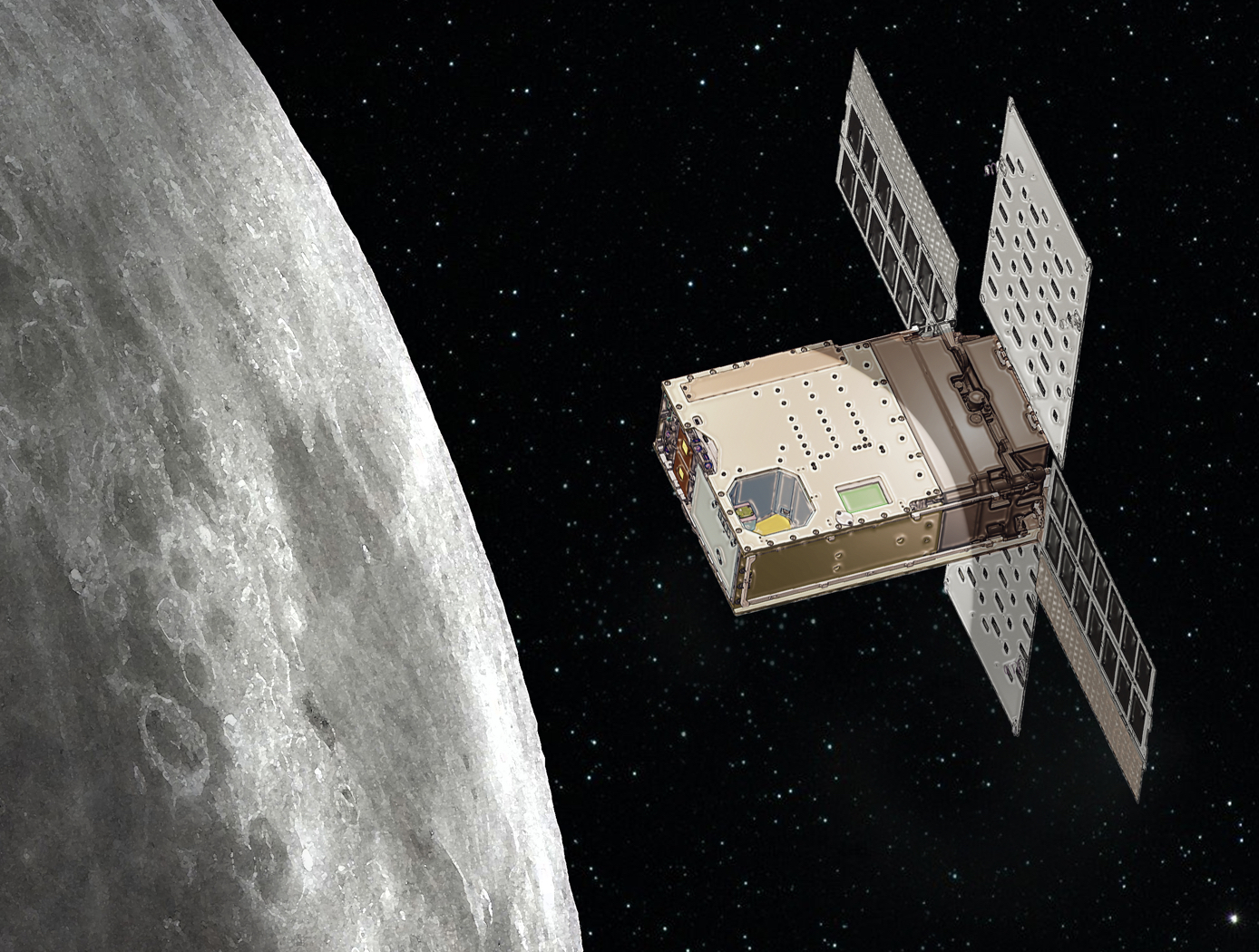
Innovators at the NASA Marshall Space Flight Center have developed the Miniature Separable Fill & Drain Valve, a manually operated, two-part valve design for CubeSat propulsion applications. Miniature propulsion systems have been an area of significant investment over recent years as rising CubeSat and SmallSat adoption has precipitated the desire to increase the utility of such spacecraft. However, miniature propulsion systems require components that are much smaller than commonly available in industry.
Due to specialized requirements for sensitivity to mass and volume as well as compatibility with the fluids used in CubeSat propulsion systems, the Miniature Separable Fill & Drain Valve was developed. This new valve design allows loading and draining of fluid while minimizing the flown component size and weight, having applications in CubeSat and miniature spacecraft propulsion systems. The valve design is also scalable, and thus may be suitable for terrestrial applications including industrial processing.
The Technology
The Miniature Separable Fill & Drain Valve consists of two halves (ground and flight). The flight half is attached to the vehicle (i.e., CubeSat), and the ground half can be inserted into the vehicle in the same port as the flight half, connecting the two halves together. In normal state, the flight half seals the flow path. When the ground half is connected, the flow path is opened, allowing connected ground support equipment to supply fluid through the valve. The valve is manually operated.
There are redundant seals to eliminate leakage around the valve, including NASA's previously-patented Low-Cost, Long Lasting Valve Seal design (Patent No. 10,197,165; see MFS-TOPS-71 in the Links section of this flyer for more information) on the flight half. This eliminates the need for a swaged assembly process and the additional hardware and equipment that are typically required in conventional, elastomeric valve seat installations. The design also includes a cap for the flight half to ensure there is no leakage in flight configuration.
The Miniature Separable Fill & Drain Valve has been prototyped and provides valuable benefits for CubeSat applications. The valve could also have applications in the industrial processing industry where low flow devices are commonly used. The design is also scalable to larger applications where the removal of the actuation device would be desired.
Benefits
- Offers miniaturization for CubeSat applications: this new valve design allows loading and draining of fluid while minimizing the flown component size and weight.
- Eliminates concerns about leakage: includes the installation of redundant seals around the valve, including a previously-patented valve seal the simplifies the seat installation process.
- Provides a scalable design for alternative applications: although the design has been optimized for CubeSat applications, the valve could also be used terrestrially in applications where the removal of the actuation device would be desired.
Applications
- Aerospace: fluid fill and drain valve for CubeSat/other miniaturized spacecraft
- Industrial machinery: low flow devices used in industrial processing
- Valves: two-part valves for space-based system as well as terrestrial systems
Similar Results

Low-Cost, Long-Lasting Valve Seal
NASA's technique simplifies the seat installation process by requiring less installation equipment, eliminating the need for unnecessary apparatus such as fasteners and retainers. Multiple seals can be installed simultaneously, saving both time and money.
NASA has tested the long-term performance of a solenoid actuated valve with a seat that was fitted using the new installation technique. The valve was fabricated and tested to determine high-cycle and internal leakage performance for an inductive pulsed plasma thruster (IPPT) application for in-space propulsion. The valve demonstrated the capability to throttle the gas flow rate while maintaining low leakage rates of less than
10-3 standard cubic centimeters per second (sccss) of helium (He) at the beginning of the valves lifetime. The IPPT solenoid actuated valve test successfully reached 1 million cycles with desirable leakage performance, which is beyond traditional solenoid valve applications requirements. Future design iterations can further enhance the valve's life span and performance.
The seat seal installation method is most applicable to small valve instruments that have a small orifice of 0.5 inches or less.

Cooperative Service Valve for In-orbit Cooperative Satellite Fueling
The CSV replaces a standard spacecraft Fill and Drain Valve to facilitate cooperative servicing. The CSV offers various advantages over standard service valves: a robotic interface, three individually actuated seals, a self-contained anti-back drive system, and built-in thermal isolation. When mounted to a spacecraft as designed, the CSV transfers all operational and induced robotic loads to the mounting structure. An anti-back drive mechanism prevents the CSV seal mechanism from inadvertent actuation. Alignment marks, thermal isolation, and a mechanical coupling capable of reacting operational and robotic loads optimize the CSV for tele-robotic operations. Unique keying of the mating interface prevents mixing of media where more than one configuration of the CSV is used. Color-coding and labels are also used to prevent operator error.
The CSV has four configurations for different working fluids, all with essentially unchanged geometry and mechanics.

Fast-Acting, Deep-Throttling Hybrid Motor
Hybrid chemical motors offer an alternative to traditional liquid or solid motors for spacecraft, missiles, rockets, or other vehicles. The key advantage of a hybrid motor is the capability to throttle the motor via active control, which cannot be done in solid propellant motors. However, rapid throttling presents significant challenges to implement in practice.
Here, NASA has combined a deep-throttling hybrid motor previously developed by Utah State University with a fast-acting digital valve design to produce a fast-acting, deep-throttling hybrid. Testing performed to-date using a prototype of the hybrid motor and digital valve design has shown the new hybrid motor to be capable of full-scale throttling twice as fast (1 second throttling compared to 2 seconds) as previous control valve designs. With optimization, there is potential full-range throttling may be further reduced to 0.5 second, a 4x improvement over previous control valve designs for hybrid motors. Additionally, smaller mid-range thrust changes have currently been measured in the 40:1 for relatively small motors (

Cryogenic Hydraulically Actuated Isolation Valve
NASA's cryogenic isolation valve technology uses solenoid valves powered by direct current (DC) electrical energy to control and redirect the energy stored in the upstream line pressure. Powering the solenoid valves only requires a DC power source capable of supplying 22 watts that can be distributed and controlled in an on/off manner. By achieving actuation using only upstream line pressure and a 22-watt DC power source, many additional support systems that are required for electromechanical and pneumatic actuation are eliminated. This reduction of parts results in several benefits, including reduced footprint, weight, and potential cost of the valve in addition to lower energy consumption.
NASA fabricated several operational prototype valves using this technology for a rocket company. The table below shows the results of tests performed on these valves under cryogenic conditions. Please contact the NASA MSFC Technology Transfer Office for additional information.

CubeSat Propulsion and Maneuvering System
Starting with a "clean sheet" for process and system design, the R5 Project Team charted a path, subsystem by subsystem, through commercial, industrial, automotive, and medical-grade components, to arrive at a functional baseline CubeSat (SX-series) bus. Although the R5 approach leans heavily on commercial-off-the-shelf (COTS) hardware, there are instances where NASA custom-designed components have been determined to be the less expensive and faster-to-develop option. Such is the case for the SX cold-gas propulsion and maneuvering system’s High-Pressure Manifold, Thruster Pod, and Threaded Jet Inserts.
The High-Pressure Manifold (MSC-27997-1) is a ported fluid distribution manifold that, relative to the SX-series CubeSat, distributes pressurized cold-gas to each Thruster Pod. Machined from high-grade aluminum, the SX-series manifold has a Maximum Design Pressure (MDP) of 3000 psig. The R5 team designed the manifold to accept a fuel tank, regulator, isolation valve, relief valve, transducer, and other COTS high-pressure fittings.
There are four component Thruster Pods (MSC-27996-1) per each SX-series CubeSat, and each Thruster Pod is fed pressurized cold-gas from the High-Pressure Manifold. These pods are designed to be 3D-printed using additively-manufactured aluminum and are later machined to add female threads for the Threaded Jet Inserts, heli-coils, and valve ports. Each pod comprises three integrated propellant conduits that independently feed the Threaded Jet Inserts. Each directional jet has an assigned thruster valve, mounted to the Thruster Pod, which throttles the pressurized cold-gas for CubeSat propulsion and maneuvering about three linear and three rotational axes.
Finally, the Threaded Jet Insert (MSC-27994-1) embodies a set-screw form factor, and relative to the SX-series CubeSat, threads into the outward-facing end of each Thruster Pod propellant conduit. Each jet is laser machined and employs an internal flow-through micro-nozzle to accelerate escaping gas fed from the thruster valve to produce thrust.
These SX-series propulsion system innovations for R5 CubeSats may also have terrestrial applications across multiple industries where, for example, targeted high-velocity gas bursts, precise pneumatic micro-force, or modular choked-flow gas metering are required.



