Search
communications
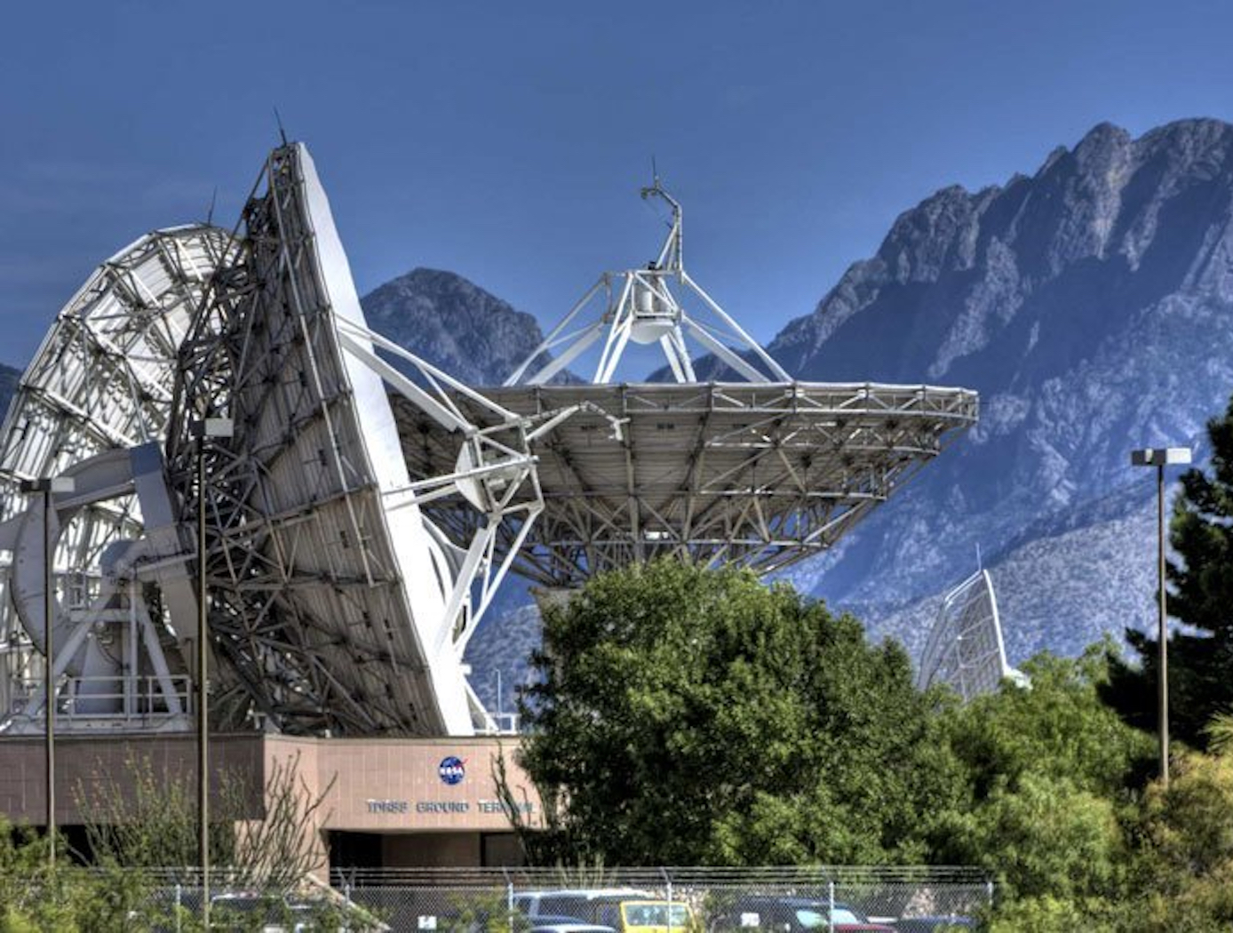
Vortex Radiometer for Wireless Communications
The Vortex Radiometer (VR) creates concentric, annular antenna beam patterns that measure sky-noise temperature. Annular antenna patterns are created by imparting orbital angular momentum into the electric field received by the antenna using spiral phase plates placed in front of the antenna aperture, generating multiple radiometer channels. Data points are then collected by plotting the measured noise temperature of each radiometer channel as a function of time. Noise temperature increases as a noise source (e.g., weather-related noise, signal interference, etc.) traverses the antenna beam patterns. An algorithm is then used to correlate noise temperature peaks in adjacent beams and to determine when a fade will occur, how long the fade will last, and how intense the fade will be. With this information, effective and efficient strategies can be implemented using cognitive communication and antenna systems to autonomously select the optimum fade-mitigation technique and parameter (e.g., increasing the transmission power, adjusting the modulation and/or coding scheme, etc.).
NASA's VR system has been prototyped, including the radiometer device and the algorithm for characterizing noise sources based on VR data. Simulations have shown that a VR system can instruct an existing cognitive antenna to switch between Ka- and X-Band communications in order to avert interference from small diameter noise sources.
Any high-performance communication systems operating in RF or optical frequencies may benefit from NASA's VR capabilities.
Sensors
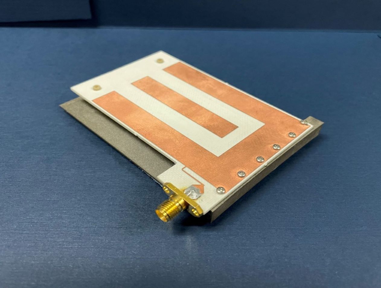
Low Mass Antenna Boosts RFID Device Performance
NASA’s HYDRA system enables a new approach in routing the RFID signal, greatly increasing extensibility and the number of antennas that can be served by a single reader. However, increasing the number of antennas in any environment is often undesirable unless the antenna size is inconspicuous. Basing this RFID dual mode antenna on a quarter-wavelength structure allows it to be smaller than an antenna designed for half-wavelength structure, reducing overall mass.
NASA’s RFID dual mode antenna is enabled by utilizing two different types of resonance modes – a “slot” mode and a microstrip “patch” mode. An innovative feed architecture allows for coupling from the RFID reader into both modes, with the impedance of each mode approximately equal at respective resonant frequencies. The antenna is designed such that each mode resonates at a different portion of the operating bandwidth, and further with each mode radiating an orthogonal polarization to the other. Frequency-hopping RFID protocols, used in conjunction with this antenna, result in the polarization diversity required for readers to reliably communicate with arbitrarily oriented RFID tags.
Numerous commercial applications exist for this RFID dual mode antenna. Examples may include usage in a multiple antenna architecture that is connected to a single reader in an open-air region, in a small, enclosed region such as a cabinet drawer, or through a combination of open and closed regions.
This RFID dual mode antenna has a technology readiness level (TRL) 7 (system prototype demonstrated in an operational environment) and is now available for patent licensing. Please note that NASA does not manufacture products itself for commercial sale.

