Search
Aerospace

Real-Time Drag Opti-mization Control Framework
According to the International Air Transport Association statistics, the annual fuel cost for the global airline industry is estimated to be about $140 billion in 2017. Therefore, fuel cost is a major cost driver for the airline industry. Advanced future transport aircraft will likely employ adaptive wing technologies that enable the wings of those aircraft to adaptively reconfigure themselves in optimal shapes for improved aerodynamic efficiency throughout the flight envelope. The need for adaptive wing technologies is driven by the cost of fuel consumption in commercial aviation. NASA Ames has developed a novel way to address aerodynamic inefficiencies experienced during aircraft operation. The real-time drag optimization control method uses an on-board, real-time sensor data gathered from the aircraft conditions and performance during flight (such as engine thrust or wing deflection). The sensor data are inputted into an on-board model estimation and drag optimization system which estimates the aerodynamic model and calculates the optimal settings of the flight control surfaces. As the wings deflect during flight, this technology uses an iterative approach whereby the system continuously updates the optimal solution for the flight control surfaces and iteratively optimizes the wing shape to reduce drag continuously during flight. The new control system for the flight control surfaces can be integrated into an existing flight control system. This new technology can be used on passenger aircraft, cargo aircraft, or high performance supersonic jets to optimize drag, improve aerodynamic efficiency, and increase fuel efficiency during flight. In addition, it does not require a specific aircraft math model which means it does not require customization for different aircraft designs. The system promises both economic and environmental benefits to the aviation industry as less fuel is burned.
aerospace
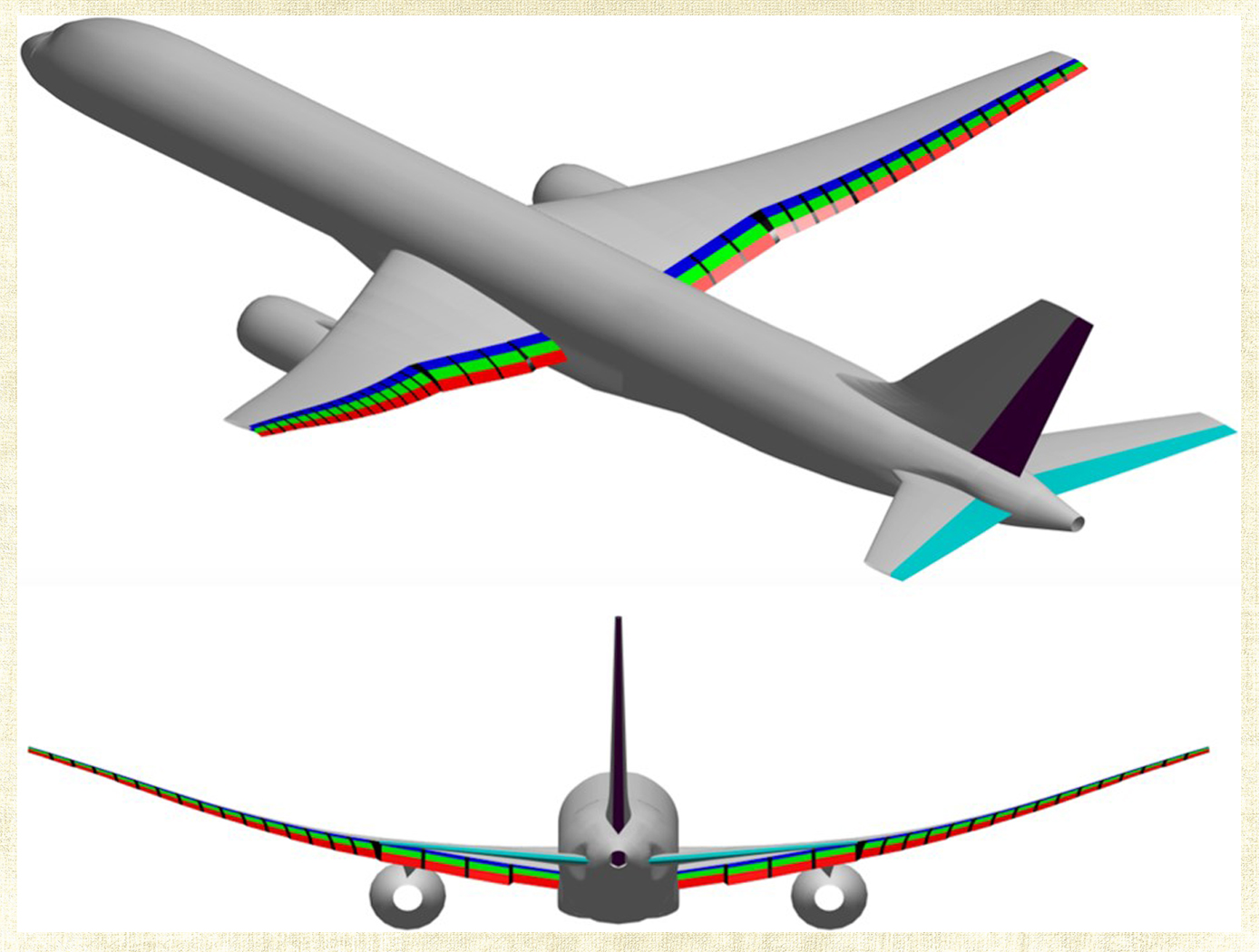
Multi-Objective Flight Control Optimization Framework
Composite materials are being used in aerospace design because of their high strength-to-weight ratio. On modern airplanes, composite wings offer a greater degree of aerodynamic efficiency due to weight savings, but at the same time introduce more structural flexibility than their aluminum counterparts. Under off-design flight conditions, changes in the wing shape due to structural flexibility cause the wing aerodynamics to be non-optimal. This effect could offset any weight saving benefits realized by the composite wings. Structural flexibility could also cause adverse interactions with flight control and structural vibration which can compromise aircraft stability, pilot handling qualities, and passenger ride quality. NASA Ames Research Center has developed a novel technology that employs a new multi-objective flight control optimization framework to achieve multiple control objectives simultaneously. This technology leverages the availability of distributed flight control surfaces in modern transports. The multi-objective flight control technology comprises the following objectives all acting in a synergistic manner: 1) traditional stability augmentation and pilot command-following flight control, 2) drag minimization, 3) aeroelastic mode suppression, 4) gust load alleviation, and 5) maneuver load alleviation. Each of these objectives can be a major control system design in its own right. Thus, the multi-objective flight control technology can effectively manage the complex interactions of the individual single-objective flight control system design and take into account multiple competing requirements to achieve optimal flight control solutions that have the best compromise for these requirements. In addition, a real- time drag minimization control strategy is included in the guidance loop. This feature utilizes system identification methods to estimate aerodynamic parameters for the on-line optimization. The aerodynamic parameters are also used in the multi-objective flight control for drag minimization and maneuver/ gust load alleviation control.
Aerospace

Improved Hypersonic Aircraft Flight Control System
NASA’s MHD patch technology is composed of two electrodes positioned a prescribed distance apart recessed into angled channels on the surface of the TPS of an aircraft or spacecraft and an electromagnetic coil placed directly below the electrodes with the magnetic field protruding out of the surface. Note that the recessed/angled MHD patch described here is a special version of the original MHD patch described in LAR-TOPS-363. During hypersonic flight, the conductive ionizing atmospheric flow over the surface permits current to flow between the two electrodes. This current is harnessed to power the electromagnet which in turn generates strong Lorentz forces that augment lift and drag forces for guidance, navigation, and control of the craft. Alternatively, the current can be used to charge a battery. Changing the size of the MHD patch (e.g., the length or distance between the electrodes), the strength of the electromagnet, or the direction of the magnetic field enables tuning of generated forces for a given craft design. Multiple MHD patches can be leveraged on a single craft.
In-silico evaluation of the non-recessed, non-angled MHD patch technology on select aeroshell designs for mock entry into planetary atmospheres has been performed. A single 1m<sup>2</sup> MHD patch exerts forces up to 200 kN under simulated Neptune atmosphere entry that can be used to control a craft.

