Search
Sensors

Dust Accumulation Sensor Provides In Situ Monitoring
Previous techniques for measuring dust accumulation, mostly de-pendent on solar cell output, were limited by their inability to distin-guish dust effects from other factors like incident radiation and radiation damage. These techniques were less effective in environ-ments with inconsistent solar flux and future missions, such as the Lunar South Pole, and lacked versatility in adapting to diverse envi-ronmental conditions. The PADS device embraces success over these challenges, and reflects enhanced features over prior iterations to also allow for space environments.
Key design features begin with the customizable mechanical design of the PADS device for use in space environments, heaters with imbedded precision temperature sensors, a selected optical coating for the device coupons that are calibrated on high-fidelity thermal modeling and validated with ground-based testing to simulate the space environment of interest (including dusting with simulants representative of the planetary-body soil/regolith), and a control circuit for precision control/matching of the thermal inputs to the sensor via the heaters. Retainers with mount isolators are implemented to ensure the stacked layers within the device do not dislodge during high vibration or gravitational loads during launch.
For operation, the PADS device is installed at the point of interest (e.g., space vehicle surface, extraterrestrial equipment) to quantify dust accumulation. Power and data transfer are done through cabling to the space vehicle system or can be provided standalone. A control circuit/algorithm adjusts the power to the heaters to precisely match the temperature setpoints. Ground testing in the simulated space environment conditions of interest creates a calibration plot of effec-tive emittance versus dust density, and allows determination of the degradation in emittance as the dust increases on the surface.
Testing on the PADS device has been completed in a simulated lunar environment and data has been collected to enable sensor calibration for its use on the Moon. It is currently poised for integration into a lander for flight testing.
Although the PADS device is intended for use in a burgeoning space industry and requisite environments – but given that the PADS device is partially comprised of programmable sensors in conjunction with optically coated coupons that can be tailored for custom use - it or its constituent components could be modified for terrestrial applications such as surface dust monitoring on photovoltaic panels or potentially combustible dust on various industrial surfaces.
Instrumentation

Waverider
WaveRider is a form of EDS technology that uses wires or insulated metal rods held a few millimeters above a substrate that is laden with dust. The wires carry a high-voltage AC square-wave signal. As the wires are moved across the surface, the dust is repelled and moves away from the wires until the whole surface is cleaned. The benefit of WaveRider over traditional EDS is that it can work on any surface, whereas traditional EDS only works with an insulating top coat. This would be a concern to any spacecraft that uses a statically dissipative surface as it's exterior top coat, and would require something like WaveRider to remove dust. Additionally, It may be beneficial to have moving wires as opposed to just having stationary electrodes for optically reliant surfaces (such as mirrors, solar panels, and helmets), as stationary wires can affect visibility. Also, because it uses wires, it can conform to irregularly shaped surfaces such as astronaut helmets or curved radiator surfaces. Moving electrodes may also offer fewer integration complexities compared with embedding stationary electrodes above the surface, since it may save weight and is structurally less complex. Electrodes on top of a surface don't place any burden on integrating it within a system (e.g., traditional EDS needs to be embedded inside cover glass for solar panels, inside O-rings/gaskets, or beneath the surface of a thermal control coating for radiators). It won't affect the properties of a coating, and there are no issues with how well it adheres to a surface like there are with traditional EDSs. Due to the nature of the technology, WaveRider could be adapted into a handheld tool that would allow much more ease of use, which is a freedom that astronauts wouldn't have if the system was built into a spacesuit or built into a machine.
Electrical and Electronics

Self-Cleaning Seals
This NASA innovation applies the concepts of electrodynamic dust shielding (EDS) to develop seals (e.g., O-rings) with active self-cleaning capabilities. NASA’s self-cleaning seals are manufactured in the following manner: A seal with a conductive surface (or otherwise fabricated to be conductive) is generated and an electrical connection, lead or electrode is attached. Next, a dielectric material is coated or placed over the conductive surface of the seal. (NOTE: Using conductive elastomer materials eliminates the need for a conductive cover layer) A high voltage (nominally >1kV) power supply is connected to the conductive layer on the seal and grounded to the metallic groove or gland that houses the seal.
Given the design, dust accumulates on the outer dielectric layer (a high-voltage insulator) of the seal. To clean the seal, a time varying alternating voltage is applied from the power supply, through the high voltage lead and onto the conductive layer of the seal. When this voltage is applied, the resulting electric field produces Coulomb and dielectrophoretic forces that cause the dust to be repelled from the sealing surface. In practice, NASA’s self-cleaning seals could be operated in continuous cleaning mode (actively repelling dust at all times, preventing it from ever contacting the seal surface) or in a periodic cleaning cycle mode (removing dust from the seal surface at regular intervals).
NASA’s self-cleaning seals have been prototyped and demonstrated to be highly effective at dust removal. The invention could serve as the basis of an active, self-cleaning seal product line marketed for in-space and/or terrestrial applications. Additionally, companies developing space assets destined for operation on dusty planetary surfaces (e.g., the Moon) may be interested in leveraging the technology to protect seals from dust/regolith accumulation, ensuring continuous low leakage operations.
Materials and Coatings

Self-Cleaning Coatings for Space or Earth
The new transparent EDS technology is lighter, easier to manufacture, and operates at a lower voltage than current transparent EDS technologies. The coating combines an optimized electrode pattern with a vapor deposited protective coating of SiO2 on top of the electrodes, which replaces either polymer layers or manually adhered cover glass (see figure on the right). The new technology has been shown to achieve similar performances (i.e., over 90% dust clearing efficiency) to previous technologies while being operated at half the voltage.
The key improvement of the new EDS coating comes from an innovative method to successfully deposit a protective layer of SiO2 that is much thinner than typical cover glass. Using vapor deposition enables the new EDS to scale more successfully than other technologies that may require more manual manufacturing methods. The EDS here has been proven to reduce dust buildup well under vacuum and may be adapted for terrestrial uses where cleaning is done manually. The coatings could provide a significant improvement for dust removal of solar cells in regions (e.g., deserts) where dust buildup is inevitable, but water access is limited. The EDS may also be applicable for any transparent surface that must remain transparent in a harsh or dirty environment.
The related patent is now available to license. Please note that NASA does not manufacturer products itself for commercial sale.
Materials and Coatings

Dust-Repelling Coating for Thermal Radiators
State-of-the-art (SOTA) EDS technology includes the addition of a dielectric substrate, the EDS electrodes, and a dielectric cover layer. Typically, this multilayer stack-up for thermal radiator EDSs are built as a stand-alone and placed directly on top of the thermal radiator base and covered with the thermal control material. This new coating system represents an alternative EDS approach that integrates with the thermal radiator's thermal control coating system. The approach involves utilizing the thermal control coating in multiple functional capacities within the EDS configuration. The thermal control coating properties are leveraged to provide electrical insulation characteristics suitable for EDS operation while maintaining thermal performance requirements.
The EDS configuration incorporates conductive elements positioned within the thermal control coating structure. The thermal control coating is applied using processes compatible with standard thermal radiator construction methods. The conductive elements are integrated during the coating application sequence. This integrated EDS approach incorporated into a thermal radiator system reduces certain components compared to SOTA EDS systems. The reduction in components offers potential benefits in system mass, thermal performance characteristics, and manufacturing complexity. The approach may reduce certain failure modes associated with interface layers and thermal expansion effects. This EDS configuration allows for enhanced flexibility in thermal radiator design parameters.
Mechanical and Fluid Systems
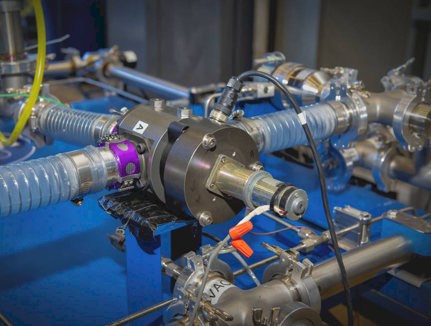
Debris-Tolerant Valve
NASA's Debris-Tolerant Valve is designed for use in machines/environments with a large quantity of airborne dust or other contaminants. Valves subjected to airborne contaminants tend to have limited lifetime due to damaged seals, bearings, and other internal components. The Debris-Tolerant Valve design addresses this problem with four core improvements over existing commercial valves that are typically used in dusty or debris-laden processes: (1) a new cylinder design that substantially decreases dust collection within the valve; (2) a rotational valve design that minimizes grinding and packing experienced by the standard ball valve; (3) the use of elastomeric seals rather than the Teflon-based seals used in existing valves which are prone to scratching and subsequent leakage; and (4) a bleed port for fluid intake that allows pressure to build slowly in the valve and eliminates the stirring of dust commonly caused by rapid inflow of air in existing valves.
The operational lifetime of NASA's Debris-Tolerant Valve exceeds the lifetime of a standard commercial valve and the existing selector valve used on the ISS by 12X and 6X, respectively. NASA's valve design has fewer parts than existing valves and could be disassembled without tools, enabling easier servicing and maintenance. The Debris-Tolerant Valve is only about one-seventh (1/7) the cost of the existing ISS selector valve.
Environment

Carbon Capture Filter
NASA’s Carbon Capture Filter was designed to trap solid carbon dust through a variety of mechanisms. These include inertial separation, flow recirculation, flow tortuosity, media filtration, and quenching of hot particles or of precursor particles from pyrolysis. The filter uses a custom-designed housing to produce a strong and large recirculating pattern to remove dust through inertial forces and confine it into a large collection cup, which is enshrouded in a cold trap (using a thermoelectric cooler) to thermally induce precipitation of the solid carbon. The flow then passes through a single stage baffle and tube filters before exiting through the outlet at the top of the housing.
During operations, gaseous carbon-containing streams enter the filter via an inlet tube at the top of the housing. The inlet tube extends down towards the bottom of the collection cup, where the high-speed stream meets a sudden perpendicular bottom wall, inducing a stagnation flow. Large particles inertially separate from the flow and impinge onto the bottom wall. The partial enclosure of the collection cup (aside from a small slit connecting it to the upper chamber) causes a recirculation bubble to form, increasing the residence time of the stream. The vortical motion of the recirculation bubble causes the large particles to spin outwards towards the walls of the collection cup. The collection cup is cooled to quench the carbon particles, causing them to precipitate out and collect on the walls of the cup. The extended residence time caused by the recirculating flow further quenches the stream. Only small particles that are entrained sufficiently by the flow make it through the slit between the collection cup and upper chamber. On the top wall of the upper chamber, an array of tubular filters collects the remaining particles before the gaseous stream exits the system.
NASA’s Carbon Capture Filter has been prototyped and undergone initial testing with simulant dust, yielding promising results. The invention is available for licensing to industry.

