Search
Aerospace
Aerospace Vehicle Entry Flightpath Control
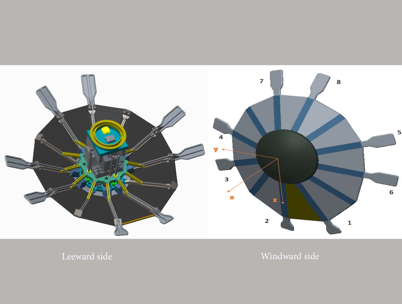
This novel flightpath control system exploits the dihedral effect to control the bank angle of the vehicle by modulating sideslip (Figure 1). Exploiting the dihedral effect, in combination with significant aerodynamic forces, enables faster bank accelerations than could be practically achieved through typical control strategies, enhancing vehicle maneuverability. This approach enables vehicle designs with fewer control actuators since roll-specific actuators are not required to regulate bank angle. The proposed control method has been studied with three actuator systems (figure below), Flaps Control System (FCS); Mass Movement Control System (MMCS); and Reaction Control System (RCS).
• FCS consists of a flap configuration with longitudinal flaps for independent pitch control, and lateral flaps generating yaw moments. The flaps are mounted to the shoulder of the vehicle’s deployable rib structure. Additionally, the flaps are commanded and controlled to rotate into or out of the flow. This creates changes in the vehicle’s aerodynamics to maneuver the vehicle without the use of thrusters.
• MMCS consists of moveable masses that are mounted to several ribs of the DEV heatshield, steering the vehicle by shifting the vehicle’s Center of Mass (CoM). Shifting the vehicle’s CoM adjusts the moment arms of the forces on the vehicle and changes the pitch and yaw moments to control the vehicle’s flightpath.
• RCS thrusters are mounted to four ribs of the open-back DEV heatshield structure to provide efficient bank angle control of the vehicle by changing the vehicle’s roll. Combining rib-mounted RCS thrusters with a Deployable Entry Vehicle (DEV) is expected to provide greater downmass capability than a rigid capsule sized for the same launch
Aerospace

Multistage Free-Flight Testing System
The disclosed technology provides a multistage system for evaluating the free-flight behavior of test articles across of the supersonic, transonic, and subsonic regimes. First, a drop platform is lifted to high altitudes using a lifting device, such as a stratospheric balloon. The drop platform houses multiple projectiles, each containing an ejection mechanism, an on-board avionics suit, and an instrumented test article. Upon reaching the target altitude via the lifting device, the drop platform releases the projectiles sequentially. Each projectile accelerates to a target speed and altitude before ejecting its test article into the freestream. The test articles, such as a scaled re-entry capsule, then collect flight data during their descent through the various Mach regimes, providing valuable insights into their flight performance under mission-relevant conditions.
This innovative testing system offers several benefits. It enables the simultaneous testing of multiple vehicles, facilitating the evaluation of design variations as well as statistical analyses of vehicle behavior. This system also provides significant cost savings in comparison to other state-of-the-art testing methods, such as ballistic range testing. Additionally, the test articles within each projectile are easily interchangeable through a simple, modular change of a support surface in the ejection mechanism. This flexibility enables the system to accommodate a range of other aerodynamic technologies, including other vehicles, parachutes, propulsion systems, and defense technologies. This system can enhance the efficiency and robustness of reentry vehicle design, testing, and simulation operations through the collection of rich, flight-relevant data.
Materials and Coatings

Flexible Phenolic Intermingled Carbon Ablators (PICA-Flex)
Flexible PICAs combine both carbon and phenolic fiber constituents during a felting process rather than introducing a phenolic through infusion processes that also uses harsh chemicals. MERINO PICA-Flex materials drastically reduces integration complexities when compared to traditional phenolic infused rigid tiles, and can eliminate the costly and time intensive phenolic infusion process, resulting in a thermal protection system (TPS) material more akin to a “blanket” than a rigid TPS. PICA-Flex encompasses a range of configurations, including a dual layer PICA-Flex material with a higher density outer layer(s) to minimize recession, a lower density PICA-Flex material with applicability to aftbody TPS, and a single piece PICA-Flex forebody. PICA-Flex is fabricated by combining by intermingling both carbon and phenolic fiber constituents during a needle punch felting process during which the fibers are made into battings, and the battings are needled together layer-by-layer to build up thickness.
Aerospace

Improved Hypersonic Aircraft Flight Control System
NASA’s MHD patch technology is composed of two electrodes positioned a prescribed distance apart recessed into angled channels on the surface of the TPS of an aircraft or spacecraft and an electromagnetic coil placed directly below the electrodes with the magnetic field protruding out of the surface. Note that the recessed/angled MHD patch described here is a special version of the original MHD patch described in LAR-TOPS-363. During hypersonic flight, the conductive ionizing atmospheric flow over the surface permits current to flow between the two electrodes. This current is harnessed to power the electromagnet which in turn generates strong Lorentz forces that augment lift and drag forces for guidance, navigation, and control of the craft. Alternatively, the current can be used to charge a battery. Changing the size of the MHD patch (e.g., the length or distance between the electrodes), the strength of the electromagnet, or the direction of the magnetic field enables tuning of generated forces for a given craft design. Multiple MHD patches can be leveraged on a single craft.
In-silico evaluation of the non-recessed, non-angled MHD patch technology on select aeroshell designs for mock entry into planetary atmospheres has been performed. A single 1m<sup>2</sup> MHD patch exerts forces up to 200 kN under simulated Neptune atmosphere entry that can be used to control a craft.
manufacturing
Woven Thermal Protection System
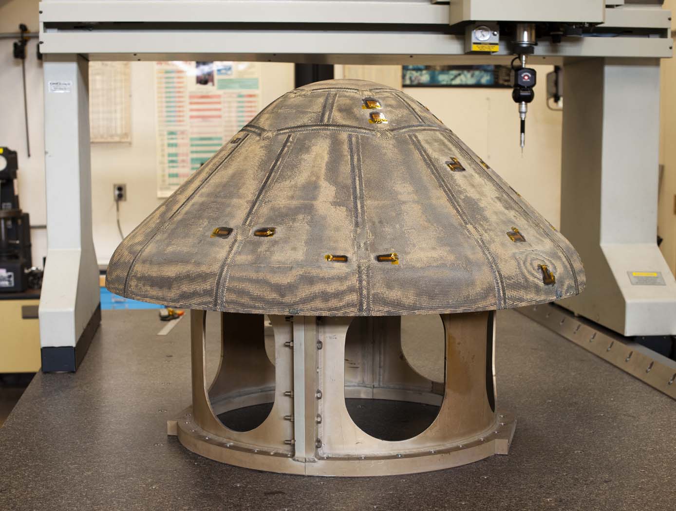
Going farther, faster and hotter in space means innovating how NASA constructs the materials used for heat shields. For HEEET, this results in the use of dual-layer, three-dimensional, woven materials capable of reducing entry loads and lowering the mass of heat shields by up to 40%. The outer layer, exposed to a harsh environment during atmospheric entry, consists of a fine, dense weave using carbon yarns. The inner layer is a low-density, thermally insulating weave consisting of a special yarn that blends together carbon and flame-resistant phenolic materials. Heat shield designers can adjust the thickness of the inner layer to keep temperatures low enough to protect against the extreme heat of entering an atmosphere, allowing the heat shield to be bonded onto the structure of the spacecraft itself. The outer and inner layers are woven together in three dimensions, mechanically interlocking them so they cannot come apart. To create this material, manufacturers employ a 3-D weaving process that is similar to that used to weave a 2-D cloth or a rug. For HEEET, computer-controlled looms precisely place the yarns to make this kind of complex three-dimensional weave possible. The materials are woven into flat panels that are formed to fit the shape of the capsule forebody. Then the panels are infused with a low-density version of phenolic material that holds the yarns together and fills the space between them in the weave, resulting in a sturdy final structure. As the size of each finished piece of HEEET material is limited by the size of the loom used to weave the material, the HEEET heat shield is made out of a series of tiles. At the points where each tile connects, the gaps are filled through inventive designs to bond the tiles together.
Aerospace
eVTOL UAS with Lunar Lander Trajectory
This NASA-developed eVTOL UAS is a purpose-built, electric, reusable aircraft with rotor/propeller thrust only, designed to fly trajectories with high similarity to those flown by lunar landers. The vehicle has the unique capability to transition into wing borne flight to simulate the cross-range, horizontal approaches of lunar landers. During transition to wing borne flight, the initial transition favors a traditional airplane configuration with the propellers in the front and smaller surfaces in the rear, allowing the vehicle to reach high speeds. However, after achieving wing borne flight, the vehicle can transition to wing borne flight in the opposite (canard) direction. During this mode of operation, the vehicle is controllable, and the propellers can be powered or unpowered.
This NASA invention also has the capability to decelerate rapidly during the descent phase (also to simulate lunar lander trajectories). Such rapid deceleration will be required to reduce vehicle velocity in order to turn propellers back on without stalling the blades or catching the propeller vortex. The UAS also has the option of using variable pitch blades which can contribute to the overall controllability of the aircraft and reduce the likelihood of stalling the blades during the deceleration phase.
In addition to testing EDL sensors and precision landing payloads, NASA’s innovative eVTOL UAS could be used in applications where fast, precise, and stealthy delivery of payloads to specific ground locations is required, including military applications. This concept of operations could entail deploying the UAS from a larger aircraft.

