Search
Robotics Automation and Control

High Stiffness Self Leveling Platform
The HSSLP employs a three-point architecture integrated with motorized jackscrews and an inertial measurement unit (IMU) to achieve automated leveling across uneven terrain. Each leg provides multiple degrees of freedom, enabling both rotational and translational adjustments to maintain a stable platform on inclines up to 15 degrees. Once positioned, the system can hold its orientation without continuous power, reducing energy consumption and improving reliability in remote or resource-limited environments. Redundancy is built into the design through multiple actuators and independent control capability, allowing the platform to maintain functionality even if one actuator fails. The design is inherently scalable, allowing adaptation for payloads ranging from small instruments to multi-ton structures without sacrificing stiffness or stability.
Originally developed for a lunar crane on the Lightweight Surface Manipulation System (LSMS), the platform has been tested in relevant environments to validate its structural integrity and load-handling performance, including successful support of a 35 kg payload at a 2-meter reach. Beyond space applications, HSSLP offers significant advantages for terrestrial industries such as construction, surveying, renewable energy, and film production. By eliminating manual adjustments and providing automated, high-load leveling capability, this technology enables faster deployment, improved safety, and greater operational efficiency in challenging environments. The HSSLP is currently assessed at a TRL 6 and is available for patent licensing.
Mechanical and Fluid Systems

ActiVator: A High-Performance Line Climber for Kite-Based Atmospheric Sensing
The ActiVator is a rigid-wing system designed to transport sensor or instrument packages along a kite line using the lift generated by apparent wind. Unlike flexible, sail-like structures, the ActiVator maintains its aerodynamic shape throughout its flight, except for a movable elevator control surface that adjusts the angle of attack to regulate aerodynamic lift. The structural design leverages principles from aircraft wing engineering, incorporating a reinforced spar capable of withstanding lift-induced bending and drag forces, an aerodynamically optimized leading edge, and a thin trailing edge to achieve higher lift coefficients than typical sail-based designs. The ActiVator can be constructed using a variety of materials, including wood with plastic covering, molded foam with reinforcements, or other lightweight composites tailored for both aerodynamic performance and structural integrity.
The control system mirrors conventional aircraft design, using a movable surface for pitch control, thereby adjusting lift to facilitate climbing or descending. Currently, the ActiVator operates via radio-controlled inputs, but it can also be configured for preprogrammed flight sequences, allowing autonomous operation without active user control.
By offering a stable, compact, and lightweight platform, the ActiVator enables high-performance instrument deployment across diverse wind conditions. Potential applications include air-quality monitoring, atmospheric boundary layer research, distributed weather observations, and remote sensing, such as optimizing the field of view and resolution of a fixed-lens camera. The technology is at Technology Readiness Level (TRL) 4 (validated in a laboratory environment) and is available for patent licensing.
Mechanical and Fluid Systems
Multi-Link Spherical Joint
The Multi-Link Spherical Joint developed at NASA Johnson Space Center provides a substantial improvement over typical joints in which only two linearly actuated links move independently from one another. It was determined that the rotation point of a trussed link needed to be collocated at a shared point in space for maximum articulation. If not allowed separate rotation, the line of action through a universal joint and hinge acts effectively as another linkage. This leads to a much more complex and uncontrollable structure, especially when considering multiple dimensions.
Comprising the Multi-Link Spherical Joint, a spherical shell encases the cupped ends of each six possible attachments and allows each of those attachments to be independently controlled and rotated without inhibiting the motion of the others. To do this, each link is precisely limited to 15 degrees of rotation off the link centerline, thus allowing a total of 30 degrees of rotation for each link. The shell-and-cup structure can handle the loads of linear actuators that may be used to control and vary the geometry of a truss system utilizing the new joint technology. The calculated operating load that the truss system must handle can be used to scale the size of the joint, further allowing customization of any potential truss system. Additionally, the incorporated linear actuators can be controlled and powered by wiring routed through the joint without putting undo stress on the wires during operation. Accordingly, this innovative joint technology enables more efficient deployment and precise operation of articulating structures.
The Multi-Link Spherical Joint is at technology readiness level (TRL) 4 (component and/or breadboard validation in laboratory environment) and is available for patent licensing. Please note that NASA does not manufacture products itself for commercial sale.
Mechanical and Fluid Systems

Modified Tuned Liquid Column Damper
When waves move a floating wind turbine, they drive fluid motion inside the MTLCD. This forces air in the vertical tanks through an orifice, increasing pressure much like a spring. As the air discharges, the fluid’s motion is damped and energy is dissipated. The MTLCD also incorporates added damping elements, such as an orifice or variable-aperture reciprocating reed valve, that create resistance to air flow, further controlling fluid motion and dissipating energy.
By integrating these modifications, the MTLCD is easily tuned to the platform’s motions, reducing dependency on platform geometry. Eliminating damping elements from the fluid removes the need for marine-grade hardware, reducing system costs. The MTLCD can also be integrated into existing ballast tanks, maximizing space efficiency with minimal added parts.
While initially developed for NASA’s Floating Wind Turbine Development project, this invention can support vibration mitigation applications across multiple industries, such as infrastructure, maritime systems, and aerospace. By enabling precise tuning of dynamic response characteristics, the MTLCD offers a compact solution for platforms requiring vibration suppression. The technology has completed preliminary design and simulation, is at a TRL 3 (proof-of-concept), and is available for patent licensing.
aerospace
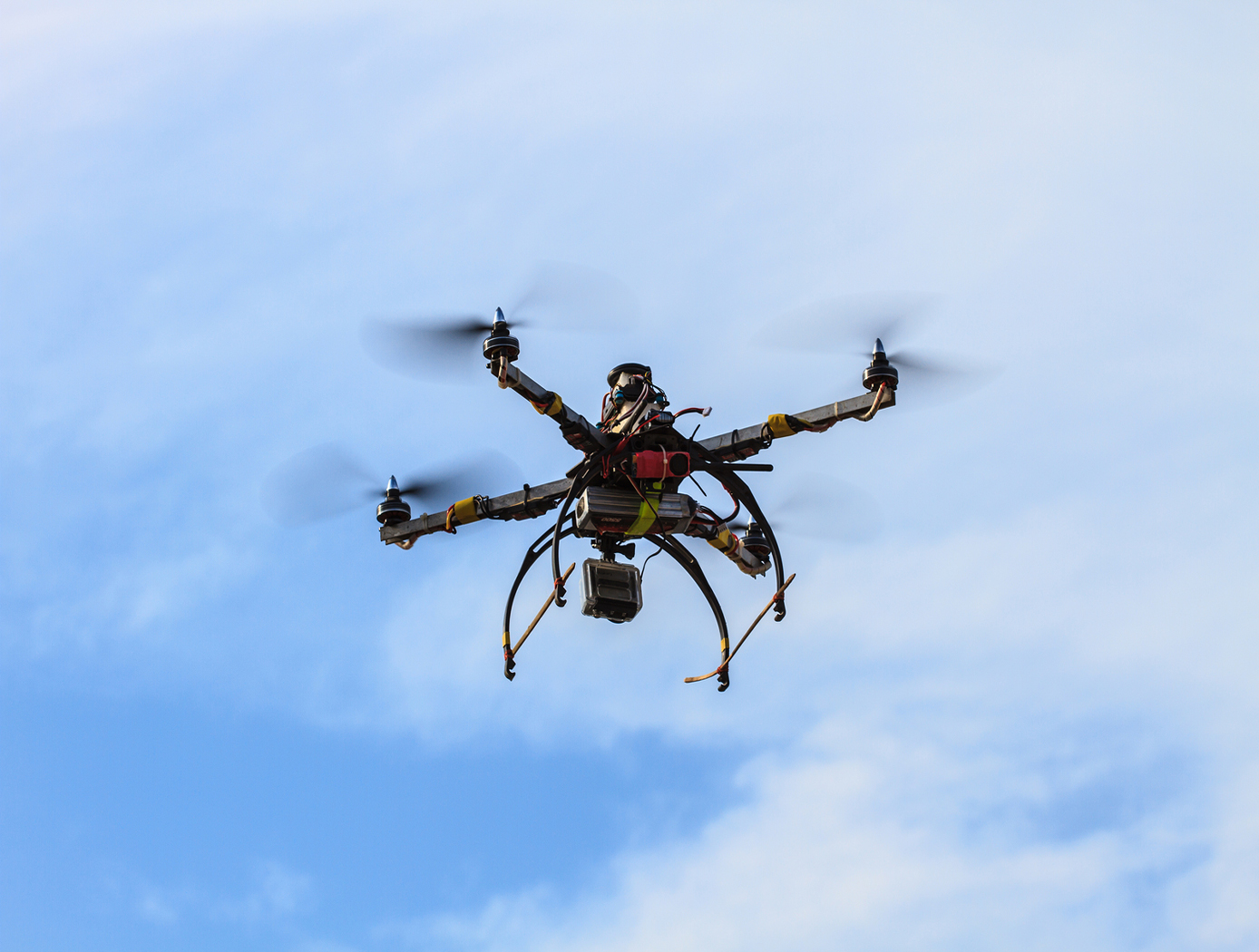
Unmanned Aerial Systems (UAS) Traffic Management
NASA Ames has developed an Autonomous Situational Awareness Platform system for a UAS (ASAP-U), a traffic management system to incorporate Unmanned Aerial Systems (UASs) into the National Airspace System. The Autonomous Situational Awareness Platform (ASAP) is a system that combines existing navigation technology (both aviation and maritime) with new procedures to safely integrate Unmanned Aerial Systems (UASs) with other airspace vehicles. It uses a module called ASAP-U, which includes a transmitter, receivers, and various links to other UAS systems. The module collects global positioning system GPS coordinates and time from a satellite antenna, and this data is fed to the UAS's flight management system for navigation. The ASAP-U module autonomously and continuously sends UAS information via a radio frequency (RF) antenna using Self-Organized Time Division Multiple Access (SOTDMA) to prevent signal overlap. It also receives ASAP data from other aircraft. In case of transmission overload, priority is given to closer aircraft. Additionally, the module can receive weather data, navigational aid data, terrain data, and updates to the UAS flight plan. The collected data is relayed to the flight management system, which includes various databases and a navigation computer to calculate necessary flight plan modifications based on regulations, right-of-way rules, terrain, and geofencing. Conflicts are checked against databases, and if none are found, the flight plan is implemented. If conflicts arise, modifications can be made. The ASAP-U module continuously receives and transmits data, including UAS data and data from other aircraft, to detect conflicts with other aircraft, terrain, weather, and geofencing. Based on this information, the flight management system determines the need for course adjustments and the flight control system executes them for a safe flight route.
Robotics Automation and Control

Robotic System for Infra-structure Reconnaissance
The robotic system is comprised of six main components: the orb that performs the reconnaissance, an orb injector housing that attaches to a piping network, a tether and reel subsystem that attaches to the back of the injector housing, a fluid injection subsystem that attaches toward the front of the injector housing, an external power and data subsystem, and associated control and monitoring software.
Usage of the system begins with an operator attaching the injector housing, with the orb stowed inside, to a flanged gate valve belonging to the piping network of concern. Requisite power, data, and fluid subsystems are attached, and the system is energized for usage. The orb is released via the tether and reel, and a controlled fluid force is imparted on the orb to help guide it along its mission. The tether supplies power and guidance to the orb, and relays real-time data back to the operator.
The orb’s interior features a modular plug-and-play architecture which may comprise COTS instrumentation for reconnaissance or investiga-tion, LIDAR, and inertial measuring and motion sensors. This instru-mentation could be used in combination with other sub-systems such as lighting, and core and sample retrieving mechanisms. These com-ponents are supported by other onboard devices such as a CPU, power source and controller, and data transmission encoders and multiplexers.
The Robotic System for Infrastructure Reconnaissance is at TRL 8 (actual system completed and "flight qualified" through test and demonstration), and is now available for licensing. Please note that NASA does not manufacture products itself for commercial sale.

