Search
Instrumentation

Projected Background-Oriented Schlieren Imaging
The Projected BOS imaging system provides a significant advancement over other BOS flow visualization techniques. Specifically, the present BOS imaging method removes the need for a physically patterned retroreflective background within the flow of interest and is therefore insensitive to the changing conditions due to the flow. For example, in a wind tunnel used for aerodynamics testing, there are vibrations and temperature changes that can affect the entire tunnel and anything inside it. Any patterned background within the wind tunnel will be subject to these changing conditions and those effects must be accounted for in the post-processing of the BOS image. This post-processing is not necessary in the Projected BOS process here.
In the Projected BOS system, a pattern is projected onto a retroreflective background across the flow of interest. The imaged pattern in this configuration can be made physically (a pattern on a transparent slide) or can be digitally produced on an LCD screen. In this projection scheme, a reference image can be taken at the same time as the signal image, facilitating real-time BOS imaging and allowing the pattern to be changed or optimized during measurements. The Projected BOS imaging technology has been proven to work by visualizing the air flow out of a compressed air canister taken with this new system. The Projected BOS is available for patent licensing.
instrumentation
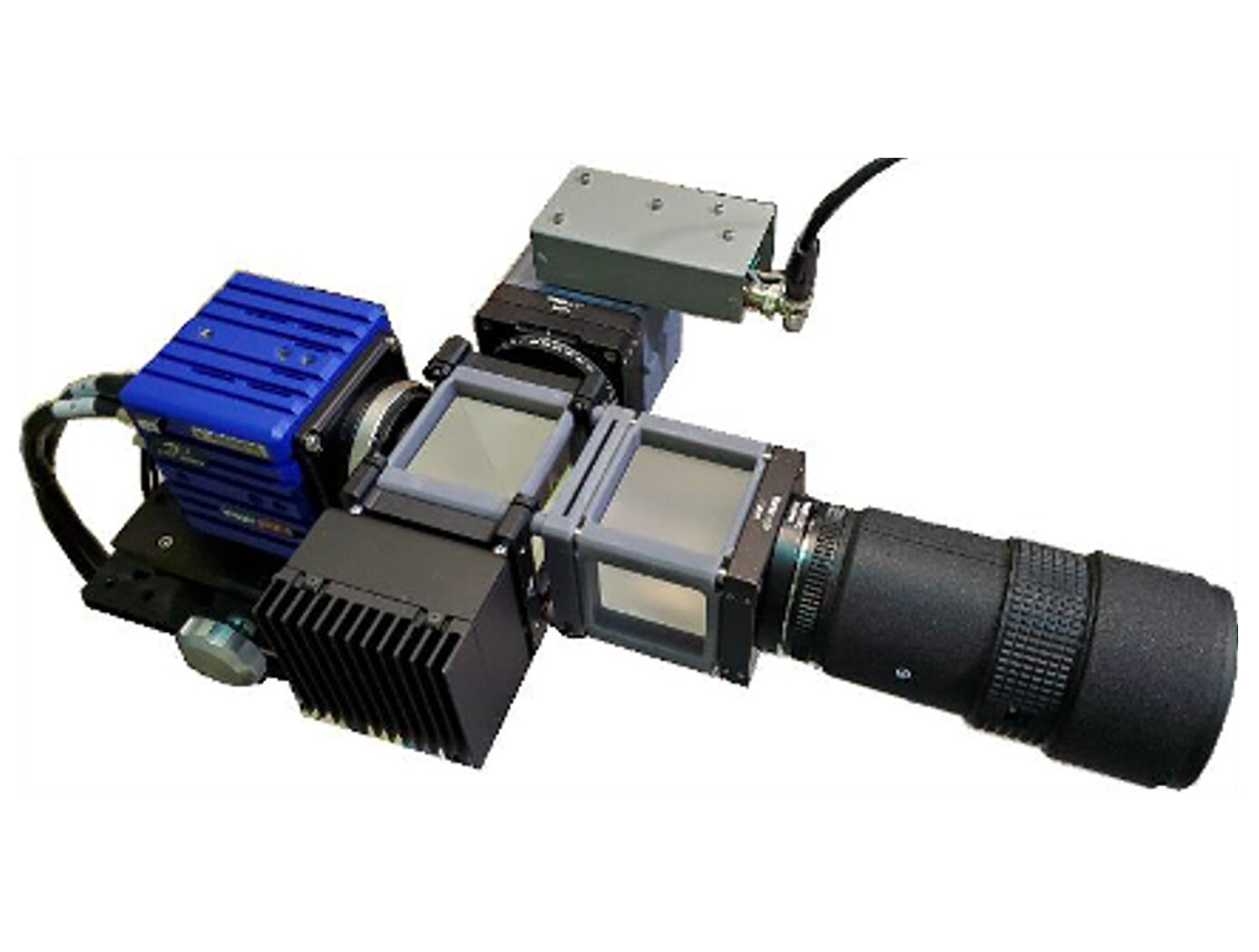
Assembly for Simplified Hi-Res Flow Visualization
NASAs single grid, self-aligned focusing schlieren optical assembly is attached to a commercial-off-the-shelf camera. It directs light from the light source through a condenser lens and linear polarizer towards a polarizing beam-splitter where the linear, vertically-polarized component of light is reflected onto the optical axis of the instrument. The light passes through a Ronchi ruling grid, a polarizing prism, and a quarter-wave plate prior to projection from the assembly as right-circularly polarized light. The grid-patterned light (having passed through the Ronchi grid) is directed past the density object onto a retroreflective background that serves as the source grid. Upon reflection off the retroreflective background, the polarization state of light is mirrored. It passes the density object a second time and is then reimaged by the system. Upon encountering the polarizing prism the second time, the light is refracted resulting in a slight offset. This refracted light passes through the Ronchi ruling grid, now serving as the cutoff grid, for a second time before being imaged by the camera.
Both small- and large-scale experimental set ups have been evaluated and shown to be capable of fields-of-view of 10 and 300 millimeters respectively. Observed depths of field were found to be comparable to existing systems. Light sources, polarizing prisms, retroreflective materials and lenses can be customized to suit a particular experiment. For example, with a high speed camera and laser light source, the system has collected flow images at a rate of 1MHz.
Materials and Coatings

Retroreflective Temperature- and Pressure-Sensitive Paints
The retroreflective-enhanced system combines PSP/TSP with specially treated glass microspheres to enable simultaneous surface and flow field measurements. The process involves a multi-layer coating system including primer, epoxy base coat, and acrylic polymer/ceramic binder, with microspheres applied while the binder retains adhesive properties. The glass microspheres may be uncoated, half-coated with aluminum, or pre-processed to be coated in another chemical. The system leverages dual optical characteristics: the underlying PSP/TSP responds to pressure and temperature changes through luminescence intensity variations at specific wavelengths, while embedded microspheres provide retroreflective properties enabling focused SAFS, shadowgraph, or BOS visualization techniques. This configuration allows simultaneous capture of on-body surface measurements and off-body flow field disturbances. The invention enables measurements from a single viewing orientation rather than requiring orthogonal optical access points. While specific excitation lighting, wavelength filtering, and camera positioning are still necessary, the system significantly streamlines experimental setup compared to traditional separate approaches.
While initially developed for aerodynamic testing and flow visualization research, this invention supports optical measurement and surface analysis applications. By enabling simultaneous measurements from a single optical access point, the retroreflective-enhanced PSP/TSP offers a streamlined solution for systems where optical access limitations are critical. The system is a TRL 6, having undergone successful validation in wind tunnel testing, and is available for patent licensing.
Optics
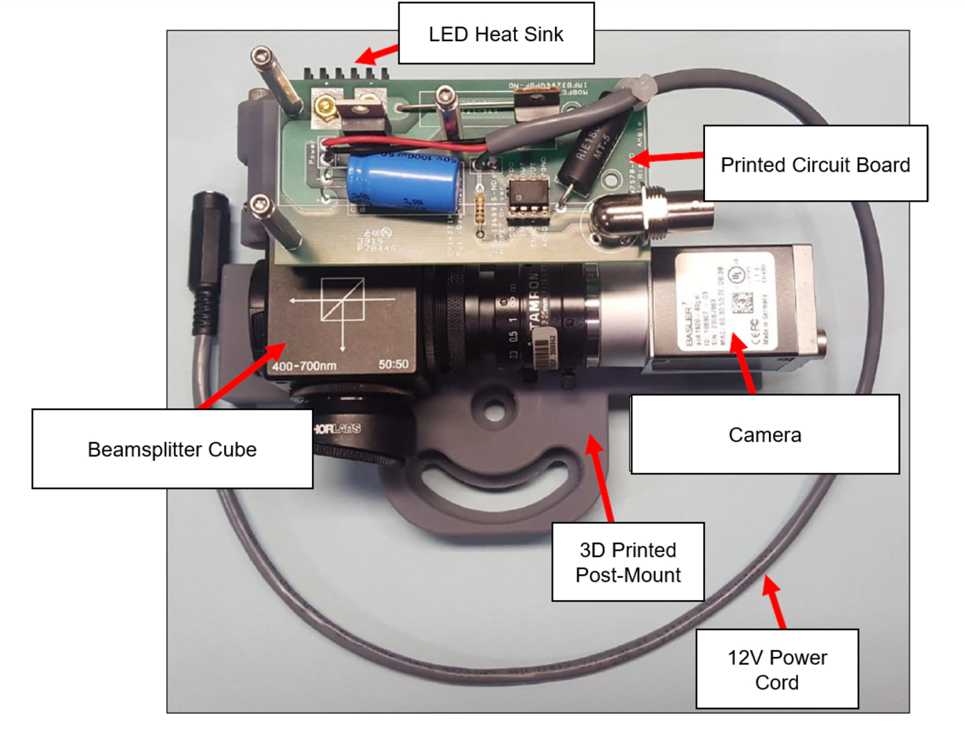
Reflection-Reducing Imaging System for Machine Vision Applications
NASA’s imaging system is comprised of a small CMOS camera fitted with a C-mount lens affixed to a 3D-printed mount. Light from the high-intensity LED is passed through a lens that both diffuses and collimates the LED output, and this light is coupled onto the cameras optical axis using a 50:50 beam-splitting prism.
Use of the collimating/diffusing lens to condition the LED output provides for an illumination source that is of similar diameter to the camera’s imaging lens. This is the feature that reduces or eliminates shadows that would otherwise be projected onto the subject plane as a result of refractive index variations in the imaged volume. By coupling the light from the LED unit onto the camera’s optical axis, reflections from windows – which are often present in wind tunnel facilities to allow for direct views of a test section – can be minimized or eliminated when the camera is placed at a small angle of incidence relative to the window’s surface. This effect is demonstrated in the image on the bottom left of the page.
Eight imaging systems were fabricated and used for capturing background oriented schlieren (BOS) measurements of flow from a heat gun in the 11-by-11-foot test section of the NASA Ames Unitary Plan Wind Tunnel (see test setup on right). Two additional camera systems (not pictured) captured photogrammetry measurements.
Optics

Filtered Ronchi Rulings for Enhanced Schlieren Imaging
The first optic is a 1D Ronchi ruling, where shortpass or longpass filters replace the traditional opaque lines in the grid pattern. The second optic is a 2D Ronchi ruling, where one set of lines is made from shortpass filters and the orthogonal set from longpass filters. By using two colors of light and a color camera in the focusing schlieren system (or a dichroic mirror with two monochrome cameras), the 1D optic enables simultaneous focusing schlieren and other co-linear techniques, while the 2D optic allows for the unambiguous measurement of two orthogonal density gradients in focusing schlieren images.
Unlike standard optical filters, which typically cover an entire substrate, these Ronchi rulings feature alternating clear and filtered regions in structured 1D or 2D patterns. By leveraging color filtering and a color camera, the 1D ruling enables simultaneous focusing schlieren and complementary optical diagnostics, such as Particle Image Velocimetry (PIV), Pressure-Sensitive Paint (PSP), and Thermal-Sensitive Paint (TSP). The 2D ruling enables simultaneous and unambiguous measurement of two orthogonal density gradients, a capability not possible with conventional Ronchi rulings. This advancement significantly improves the accuracy and efficiency of schlieren-based flow measurements. The types of filters are not just limited to shortpass and longpass coatings, but could include notch, bandpass, and multiple-bandpass filter coatings as well.
This design expands the utility of schlieren imaging in high-speed aerodynamics, combustion diagnostics, and other fluid dynamics applications. This Ronchi ruling methodology is at TRL 4 (component and/or breadboard validation in a lab environment) and is available for patent licensing.
Instrumentation

Digital Projection Focusing Schlieren System
NASA’s digital projection focusing Schlieren system is attached to a commercial-off-the-shelf camera. For focusing Schlieren measurements, it directs light from the light source through a condenser lens and linear polarizer towards a beam-splitter where linear, vertically-polarized component of light is reflected onto the optical axis of the instrument. The light passes through the patterned LCD element, a polarizing prism, and a quarter-wave plate prior to projection from the assembly as left- or right-circularly polarized light. The grid-patterned light (having passed through the LCD element) is directed past the density object onto a retroreflective background (RBG) that serves as the source grid. Upon reflection off the RBG, the polarization state of light is mirrored. It passes the density object a second time and is then reimaged by the system. Upon encountering the polarizing prism the second time, the light is slightly offset. This refracted light passes through the LCD element, now serving as the cutoff grid, for a second time before being imaged by the camera.
The LCD element can be programmed to display a variety of grid patterns to enable sensitivity to different density gradients. The color properties of the LCD can be leveraged in combination with multiple colored light sources to enable simultaneous multi-color, multi-technique data collection.
This system is ready for integration into commercial flow visualization and diagnostic equipment, offering manufacturers and research facilities an efficient, cost-effective solution for multi-technique imaging. The Schlieren system is currently available for patent licensing.

