Search
Optics

Nested Focusing Optics for Compact Neutron Sources
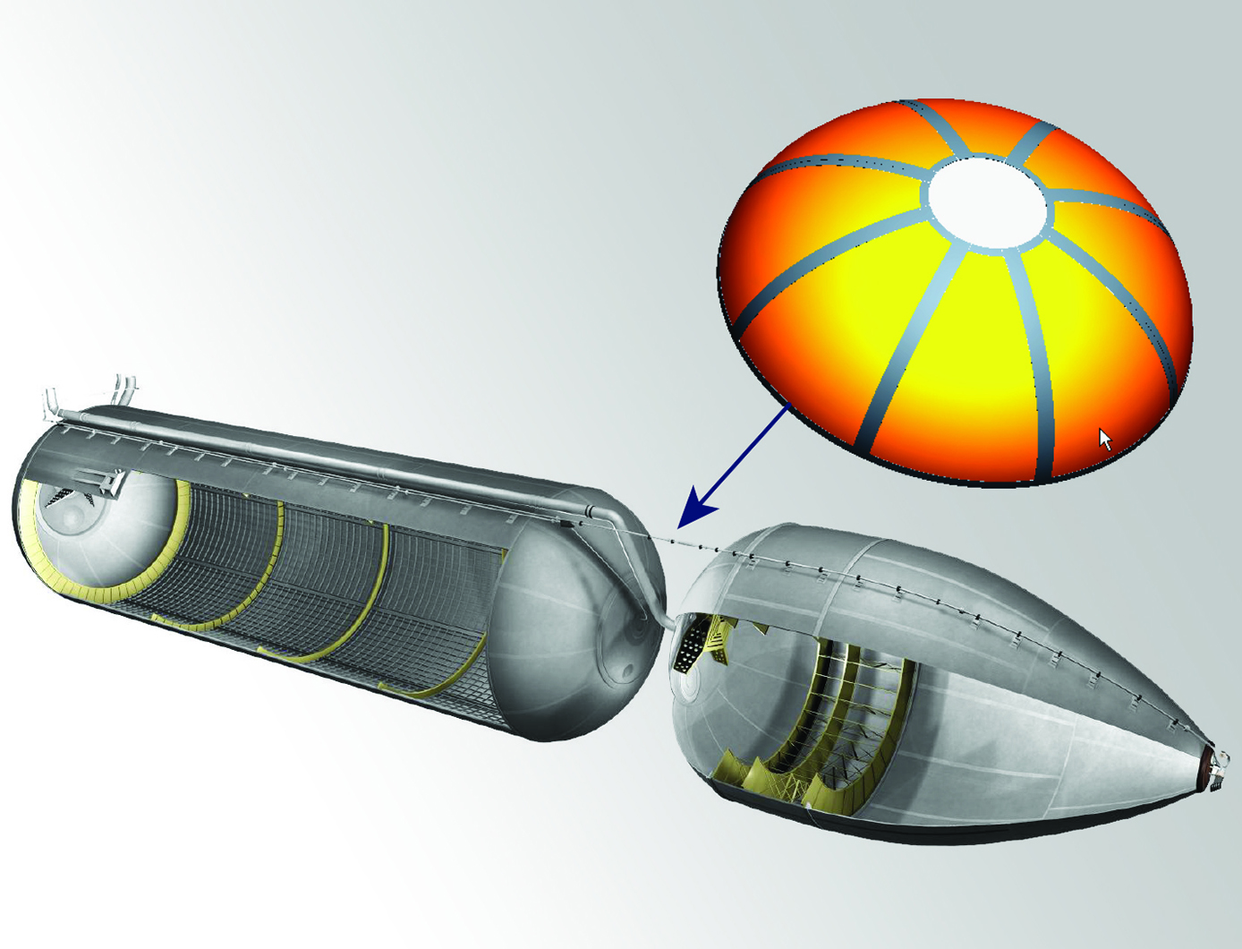
Conventional neutron beam experiments demand high fluxes that can only be obtained at research facilities equipped with a reactor source and neutron optics. However, access to these facilities is limited. The NASA technology uses grazing incidence reflective optics to produce focused beams of neutrons (Figure 1) from compact commercially available sources, resulting in higher flux concentrations. Neutrons are doubly reflected off of a parabolic and hyperbolic mirror at a sufficiently small angle, creating neutron beams that are convergent, divergent, or parallel. Neutron flux can be increased by concentrically nesting mirrors with the same focal length and curvature, resulting in a convergence of multiple neutron beams at a single focal point. The improved flux from the compact source may be used for non-destructive testing, imaging, and materials analysis.
The grazing incidence neutron optic mirrors are fabricated using an electroformed nickel replication technique developed by NASA and the Harvard-Smithsonian Center for Astrophysics (Figure 2). A machined aluminum mandrel is super-polished to a surface roughness of 3-4 angstroms root mean square and plated with layers of highly reflective nickel-cobalt alloy. Residual stresses that can cause mirror warping are eliminated by periodically reversing the anode and cathode polarity of the electroplating system, resulting in a deformation-free surface. The fabrication process has been used to produce 0.5 meter and 1.0 meter lenses.
manufacturing

Ultrasonic Stir Welding
Ultrasonic Stir Welding is a solid state stir welding process, meaning that the weld work piece does not melt during the welding process. The process uses a stir rod to stir the plasticized abutting surfaces of two pieces of metallic alloy that forms the weld joint. Heating is done using a specially designed induction coil. The control system has the capability to pulse the high-power ultrasonic (HPU) energy of the stir rod on and off at different rates from 1-second pulses to 60-millisecond pulses. This pulsing capability allows the stir rod to act as a mechanical device (moving and stirring plasticized nugget material) when the HPU energy is off, and allowing the energized stir rod to transfer HPU energy into the weld nugget (to reduce forces, increase stir rod life, etc.) when the HPU energy is on. The process can be used to join high-melting-temperature alloys such as titanium, Inconel, and steel.
manufacturing
Improving Formability of Al-Li Alloys
Via this NASA innovation, a product is first heated to a temperature within the range of 204 to 343 degrees C for an extended soak of up to 16 hours. The product is then slowly heated to a second temperature within the range of 371 to 482 degrees C for a second soak of up to 12 hours. Finally, the product is slowly cooled to a final soak temperature of 204 to 343 degrees C before cooling to room temperature. The product so treated will exhibit greatly improved formability.
To date, the low formability issue has limited the use of lightweight Al-Li alloys for large rocket fuel tank dome applications. Manufacturing a dome by stretch forming typically requires multiple panels as well as multiple welding and inspection steps to assemble these panels into a full-scale fuel tank dome. Complex tensile and bending stresses induced during the stretch forming operations of Al-Li alloys have resulted in high rates of failure for this process. To spin form a large rocket dome, the spin blank must be prepared by joining smaller plates together using friction stir welding. However, friction stir welding produces a distinct metallurgical structure inside and around the friction stir weld that makes it very susceptible to cracking during spin forming.
Manufacturing
Friction Stir Deposition Innovations
Metal additive manufacturing may be limited by build volumes (i.e., it can be hard to make large parts), post-processing requirements, and upfront costs to buy capital equipment. The two NASA-developed technologies are add-on tools for FSW systems (reducing costs), do not require a printer or print bed, and produce parts with high quality surface finishes.
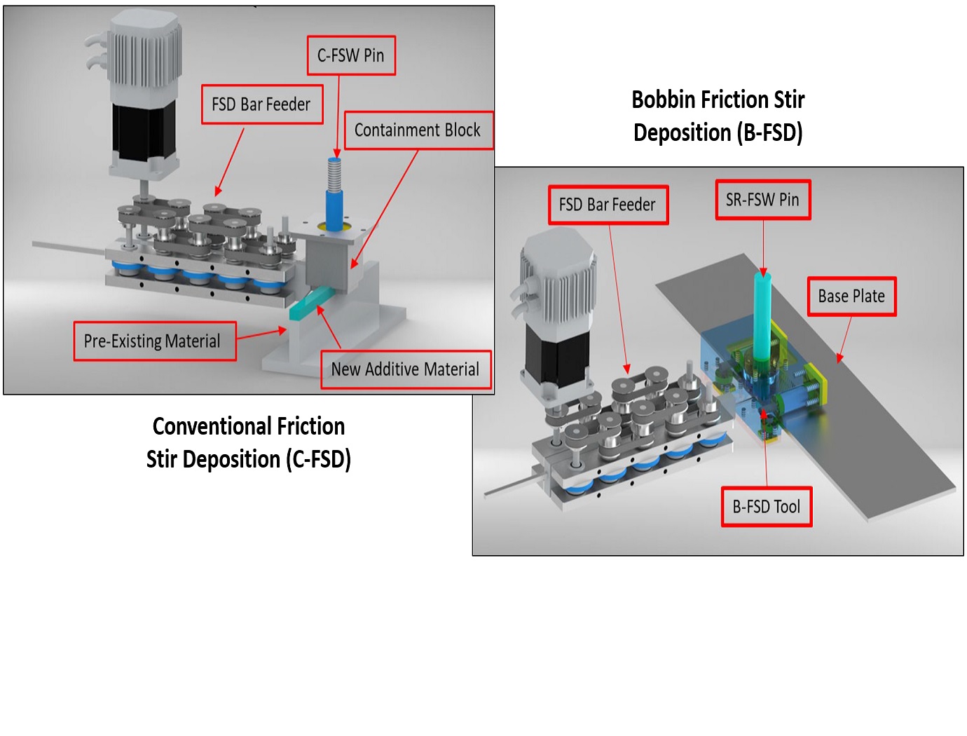
The C-FSD attachment includes a non-rotating block through which the C-FSW rotating pin is threaded, and a containment plate to hold the plasticized metal within the system. In this technique, raw metal feedstock is fed into one end of the non-rotating block, is heated and plasticized by the C-FSW pin, and is driven out the other side of the block. The C-FSW pin is used to join the new material to the pre-existing layer.
The B-FSD tool uses a dual-shoulder design to print outward from the edge of the base panel. The B-FSD process uses the same feed system as the C-FSD, but utilizes the bobbin/SR-FSW pin's dual shoulders (i.e., containing the metal on both the top and bottom) enabling more complex structures to be made, and the ability to print varying thickness depositions in a single pass.
The Additive C-FSD and B-FSD end effector tools are both at technology readiness level (TRL) 4 (component and/or breadboard validation in laboratory environment) and are available for patent licensing.
Manufacturing
Conventional friction stir extrusion machine
Typical metal extrusion relies on heating large metal billets and then forcing the heated billet through a dye to extrude the geometry and length of interest. These processes require high energy inputs, expensive machinery to heat and manipulate the billets, and the length of the final part is limited by billet size. Thus, new ways to cost effectively and efficiently produce extruded parts are needed.
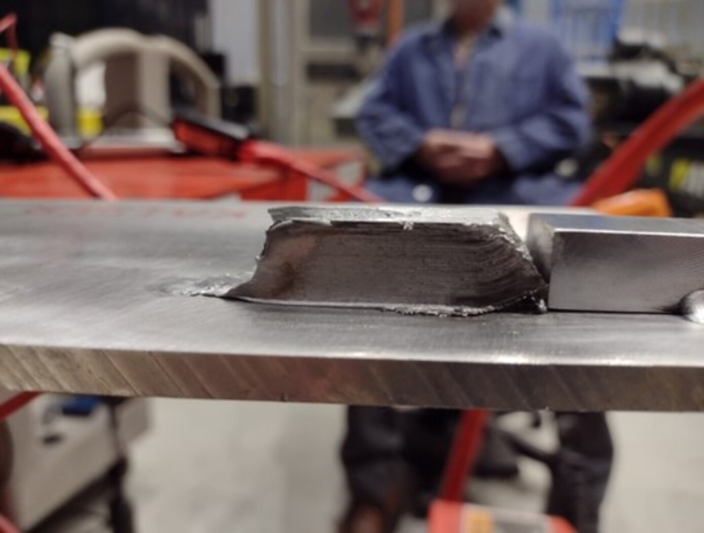
The C-FSE machine developed by NASA encompasses a non-rotating extrusion block and a rotating pin that extends through the chamber. The extrusion block has a close tolerance fit to the rotating pin to prevent material from escaping from the ends of the block. Raw metal feedstock is fed into one side of the chamber, the rotating pin interacts with the metal to generate plastic deformation and heat, and the metal is driven out the other side of the extrusion block through a customizable die. As the C-FSE machine does not require pre-heated billets, the extruded parts may be of any desired length. Further, the extrusion machine is modular in nature and may be retrofitted onto an existing FSW system, and the die may be easily replaced for varying extrusion geometries. The C-FSE machine has been prototyped and used to produce freestanding metal parts.
The C-FSE machine is at technology readiness level (TRL) 4 (component and/or breadboard validation in laboratory environment) and is available for patent licensing.

