Gear Bearings
mechanical and fluid systems
Gear Bearings (GSC-TOPS-12)
Increased capacity and performance with reduced size, weight, & cost
Overview
NASA Goddard Space Flight Center (GSFC) invites companies to license the revolutionary gear bearing technology. This technology represents a mechanical architecture breakthrough by combining gear and bearing functions into a single unit that significantly improves gear drives across the board for electrical, internal combustion, and turbine motors. The gear bearing design incorporates rifle-true anti-backlash, improved thrust bearing performance, and phase-tuning techniques for superior low-speed reduction. Because it combines gear and bearing functions, it reduces weight, number of parts, size, and cost, while also increasing load capacity and performance.
The Technology
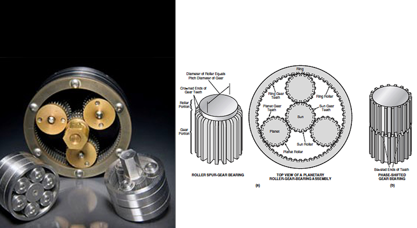
These patented gear bearings provide superior speed reduction in a small package. They form rolling friction systems that function both as gears and bearings and are compatible with most gear types, including spur, helical, elliptical, and bevel gears. These self-synchronized components can be in the form of planets, sun, rings, racks, and segments thereof. The design reduces micro chatter and eliminates rotational wobble to create smooth and precise control. It offers tighter mesh, more even gear loading, and reduced friction and wear.
Gear bearings eliminate separate bearings, inner races, and carriers, as well as intermediate members between gears and bearings. Load paths go directly from one gear bearing component to another and then to ground. By incorporating helical gear teeth forms (including herringbone), gear bearings provide outstanding thrust bearing performance. They also provide unprecedented high- and low-speed reduction through the incorporation of phase tuning. Phase tuning allows differentiation in the number of teeth that must be engaged govbetween input and output rings in a planetary gearset, enabling successful reduction ratios of 2:1 to 2,000:1. They provide smooth and accurate control with rifle-true anti-backlash. This produces a planetary transmission with zero backlash. The gear bearing technology is based on two key concepts: the roller gear bearing and the phase-shifted gear bearing. All designs are capable of efficiently carrying large thrust loads.
Existing gear systems have drawbacks including weak structures, large size, and poor reliability, as well as high cost for some types (e.g., harmon-ic drives). Gear bearings solve these problems with simpler construction, fewer parts, and superior strength.
By selecting the appropriate manufacturing method and materials, gear bearings can be tailored to benefit any application, from toys to aircraft.


Benefits
- Precise control: Zero backlash results in smoother operation and superior control
- Improved thrust bearing: Gear teeth design gives superior thrust bearing performance
- Unprecedented speed reduction: Significant reduction ratios at both low and high speeds is achieved
- Less noise and vibration: More evenly distributed planet loading reduces cyclic loading and rough spots, reducing noise and vibration
- Fewer fatigue failures: Reduced cyclic loading decreases susceptibility to fatigue failures
- Low cost, simple design: Simplified design reduces materials, weight, and cost
- High strength: More structurally rigid and provide higher load capacity compared to fixed planetary designs
- Versatile: Can be applied to many types of motions including linear, rotary, or motion hybrids
- Enables all-electric actuator systems: Can eliminate hydraulics in many applications
Applications
- Transportation (including automotive, aircraft, marine, and rail): Transmissions, electric windows, windshield wipers, steering mechanisms, alternators/generators, engines and propellers, control systems, landing gear, door openers, rudders/ steering/leveling controls, winches, rail switching systems
- Power tools: Garden equipment, lawn mowers, chain saws, log splitters, power drills, car jacks, screw drivers, powered garage doors, powered winches, etc.
- Industrial machinery: Power presses, lathes and grinders, slitting and rolling equipment, construction equipment, lifting and handling equipment
- Farm equipment: Tractors, harvesters, hay rollers
- Toys: Electric robots, cars, and other motorized toys
|
Tags:
|
Similar Results

Reverse Vortex Ring (RVR)
Vibration problems, which occur more frequently in high power to weight machines, often lead to costly down time, subsequent redesign, and, in some instances, catastrophic failure. A disproportionate number of vibration problems in rotating machinery can be attributed to highly pre-swirled fluid entering tight clearance locations such as seals and fluid bearings. The relationship between high fluid pre-swirl and undesirable vibration issues is clear. Machines with high levels of fluid pre-swirl are more susceptible to instabilities and vibration problems.
A top priority in rotor dynamic design, therefore, is to develop devices to minimize the level of fluid pre-swirl entering tight clearance locations. The RVR was designed to condition the flow prior to entering the seal (or axial flow fluid-film bearing) so that the flow through the annular clearance is at a minimum purely axial. While conventional swirl brakes have only been shown to reduce pre-swirl by up to 30%, the RVR can actually reverse the direction of the swirl, so that circumferential fluid velocity flows in a direction counter to shaft rotation. Thus, a classic detriment to rotating machinery has now become an asset to ameliorate vibration issues through the RVR.
The RVR is axially efficient, typically increasing the axial length of a smooth annular seal on the order of 10-12%.
The RVR has been extensively tested and is now in use at NASA.

Friction Stir Deposition Innovations
Metal additive manufacturing may be limited by build volumes (i.e., it can be hard to make large parts), post-processing requirements, and upfront costs to buy capital equipment. The two NASA-developed technologies are add-on tools for FSW systems (reducing costs), do not require a printer or print bed, and produce parts with high quality surface finishes.
The C-FSD attachment includes a non-rotating block through which the C-FSW rotating pin is threaded, and a containment plate to hold the plasticized metal within the system. In this technique, raw metal feedstock is fed into one end of the non-rotating block, is heated and plasticized by the C-FSW pin, and is driven out the other side of the block. The C-FSW pin is used to join the new material to the pre-existing layer.
The B-FSD tool uses a dual-shoulder design to print outward from the edge of the base panel. The B-FSD process uses the same feed system as the C-FSD, but utilizes the bobbin/SR-FSW pin's dual shoulders (i.e., containing the metal on both the top and bottom) enabling more complex structures to be made, and the ability to print varying thickness depositions in a single pass.
The Additive C-FSD and B-FSD end effector tools are both at technology readiness level (TRL) 4 (component and/or breadboard validation in laboratory environment) and are available for patent licensing.

Axial Magnetic Flux Airflow Integrated Compressor-Generator-Motor Turbojet
The innovation uses the rotating blades of the compressor section to act as structural support for the generator. Since the compressor is the coolest part of the engine, it will reduce the potential for interference with magnetics and associated curie points of the permanent magnets. The placement of the generator in the cooler part of the engine flowpath (fan or compressor) will also improve the electrical insulation system's degradation and serve to improve overall system lifetime.
The configuration proposed by Armstrong's design would be an axial magnetic flux permanent magnet generator or motor. The electrical/mechanical interface could serve to deliver power to the shaft of the turbojet/fan or extract power from the shaft.
This axial electromagnetic flux design is more efficient for the combined function of aero-thermal heat transfer and generation of electricity. This is due to the relative amount of available cooling surface area, which has an advantage over radial designs given the total system volumetric aspect ratio of the generator/compressor section. When the system is viewed as a thermodynamic cycle, it is more efficient because it is essentially a regenerative cycle, with the heat of generation being fed back into the cycle instead of being released into the ambient surroundings

Oil-Free Lubricants
In applying PS400 using the plasma spray-coating process, a 0.010 inch layer is deposited onto a metal surface. This composite coating often includes a metallic-based binder, a metal-bonded hardener, a high-temperature lubricant, and/or a low- temperature lubricant. PS400's improved metallic-based binder alloy greatly increases the structural strength and durability of the composite with respect to the operating temperature and the bearing load, and provides superior dimensional stability. PS400's metal-bonded oxide hardening agent provides additional hardness, wear resistance, and thermal stability, while also exhibiting a low coefficient of friction when used in sliding contacts. It is also significantly less expensive in terms of both acquisition and grinding processes.
Depending on the desired environment, high- and low-temperature lubricants may be added to the composite coating. The preferred high-temperature lubricant is a metal fluoride and the optional optional low-temperature lubricant is composed of metals, such as silver or copper, that are soft enough to provide lubrication at low temperature while maintaining oxidation resistance with a sufficiently high melting point. These qualities permit the materials to be used over a broad temperature range. Once the spray coating has been applied, the metal surface is ground and polished to produce a smooth, self-lubricating surface before use. Unlike some coatings that must be diamond-ground, PS400 is readily ground with a substantially less expensive abrasive, such as silicon carbide. This grinding process generally yields a coating thickness of 200 to 400 micrometers.
In instances when a coating is not convenient or possible, powder metallurgy techniques using PM400 can be used to make freestanding self-lubricating components such as bushings and wear plates.

Small Spacecraft Electric Propulsion (SSEP) Technology Suite
Innovators at GRC have developed a suite of SSEP technologies for small, low-power spacecraft using Hall effect thrusters including a high propellant throughput small spacecraft electric propulsion thruster (LEW-TOPS-158), a power processing unit for SSEP (LEW-TOPS-157), an anode manifold plug for Hall effect thrusters (LEW-TOPS-159), and additional Hall effect technologies (LEW-TOPS-34). See the Additional Information section at the bottom of the page for more information on each technology suite component.
GRC is making these technologies available to U.S. companies through a no-cost*, non-exclusive license agreement and companion Space Act Agreement. Licensees may receive a comprehensive package of design and process documents including issued and pending patents, design drawings, materials specifications, and test data. Licensees will assist in defining system requirements and creating new platforms to use the SSEP technologies. This streamlined, collaborative commercialization strategy helps satisfy NASA exploration and science mission requirements while improving U.S. competitiveness in the global electric propulsion market and improving the success of new electric propulsion developments. Working alongside our licensees, GRC hopes to generate a compendium of SSEP knowledge as a living document, maintained by all users in a consortia-like environment.
*Although the license and Space Act Agreement are no cost to the licensees, licensees would be responsible for setting up and maintaining an EAR restricted file sharing space.


