Search
manufacturing
.jpg)
Interim, In Situ Additive Manufacturing Inspection
The in situ inspection technology for additive manufacturing combines different types of cameras strategically placed around the part to monitor its properties during construction. The IR cameras collect accurate temperature data to validate thermal math models, while the visual cameras obtain highly detailed data at the exact location of the laser to build accurate, as-built geometric models. Furthermore, certain adopted techniques (e.g., single to grouped pixels comparison to avoid bad/biased pixels) reduce false positive readings.
NASA has developed and tested prototypes in both laser-sintered plastic and metal processes. The technology detected errors due to stray powder sparking and material layer lifts. Furthermore, the technology has the potential to detect anomalies in the property profile that are caused by errors due to stress, power density issues, incomplete melting, voids, incomplete fill, and layer lift-up. Three-dimensional models of the printed parts were reconstructed using only the collected data, which demonstrates the success and potential of the technology to provide a deeper understanding of the laser-metal interactions. By monitoring the print, layer by layer, in real-time, users can pause the process and make corrections to the build as needed, reducing material, energy, and time wasted in nonconforming parts.
mechanical and fluid systems

Micro scale electro hydrodynamic (EHD) modular cartridge pump
NASA GSFCs EHD pump uses electric fields to move a dielectric fluid coolant in a thermal loop to dissipate heat generated by electrical components with a low power system. The pump has only a few key components and no moving parts, increasing the simplicity and robustness of the system. In addition, the lightweight pump consumes very little power during operation and is modular in nature. The pump design takes a modular approach to the pumping sections by means of an electrically insulating cartridge casing that houses the high voltage and ground electrodes along with spacers that act as both an insulator and flow channel for the dielectric fluid. The external electrical connections are accomplished by means of commercially available pin and jack assemblies that are configurable for a variety of application interfaces. It can be sized to work with small electric components or lab-on-a-chip devices and multiple pumps can be placed in line for pumping greater distances or used as a feeder system for smaller downstream pumps. All this is done as a one-piece construction consolidating an assembly of 21 components over previous iterations.
Power Generation and Storage
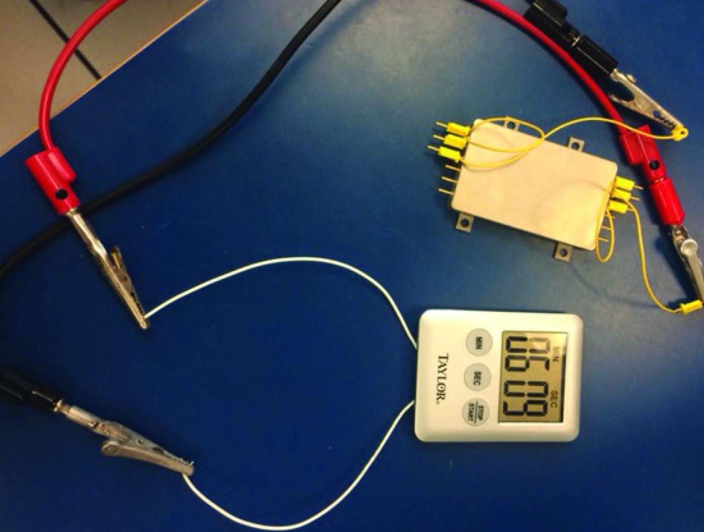
Internal Short Circuit Testing Device to Improve Battery Designs
Astronauts' lives depend on the safe performance and reliability of lithium-ion (Li-ion) batteries when they are working and living on the International Space Station. These batteries are used to power everything such as communications systems, laptop computers, and breathing devices. Their reliance on safe use of Li-ion batteries led to the research and development of a new device that can more precisely trigger internal short circuits, predict reactions, and establish safeguards through the design of the battery cells and packs. Commercial applications for this device exist as well, as millions of cell phones, laptops, and electronic drive vehicles use Li-ion batteries every day. In helping manufacturers understand why and how Li-ion batteries overheat, this technology improves testing and quality control processes.
The uniqueness of this device can be attributed to its simplicity. In a particular embodiment, it is comprised of a small copper and aluminum disc, a copper puck, polyethylene or polypropylene separator, and a layer of wax as thin as the diameter of one human hair. After implantation of the device in a cell, an internal short circuit is induced by exposing the cell to higher temperatures and melting the wax, which is then wicked away by the separator, cathode, and anode, leaving the remaining metal components to come into contact and induce an internal short. Sensors record the cell's reactions. Testing the battery response to the induced internal short provides a 100% reliable testing method to safely test battery containment designs for thermal runaway.
This jointly developed and patented technology is available for your company to license and develop into a commercial product. NASA does not manufacture products for commercial sale.
power generation and storage

Solar Powered Carbon Dioxide (CO2) Conversion
This technology consists of a photoelectrochemical cell composed of thin metal oxide films. It uses sunlight (primarily the ultraviolet (UV), visible and Infrared (IR) portions)) and inexpensive titanium dioxide composites to perform the reaction. The device can be used to capture carbon dioxide produced in industrial processes before it is emitted to the atmosphere and convert it to a useful fuel such as methane. These devices can be deployed to the commercial market with low manufacturing and materials costs. They can be made extremely compact and efficient and used in sensor and detector applications.
Power Generation and Storage
Novel, Solid-State Hybrid Ultracapacitor Battery
The subject technology is an extension of closely related, solid-state ultracapacitor innovations by the same team of inventors. The primary distinction for this specific technology is the addition of co-dopants to affect the dielectric behavior of the barium titanatebased perovskite materials. These co-dopants include lanthanum and other rare earths as well as hydroxyl ions. The materials are processed at the nano scale, and are subjected to carefully designed thermal treatments as well.
The presence of the hydroxyl ions has been shown to provide several orders of magnitude increase in the capacitance of the dielectric material. Additionally, these high capacitance values are obtained at relatively low voltages found in current consumer and industrial electronics.
The capacitors tested to date are simple, single-layer devices. Ultimately, a range of manufacturing methods are possible for making commercial devices. Features of the technology enable manufacturing via traditional thick-film processing methods widely used in the capacitor industry, or via advanced printing methods for state-of-the-art printed electronics.
Future efforts will be made to advance the manufacturing and packaging processes to increase device energy density, including multilayer devices and packages
power generation and storage

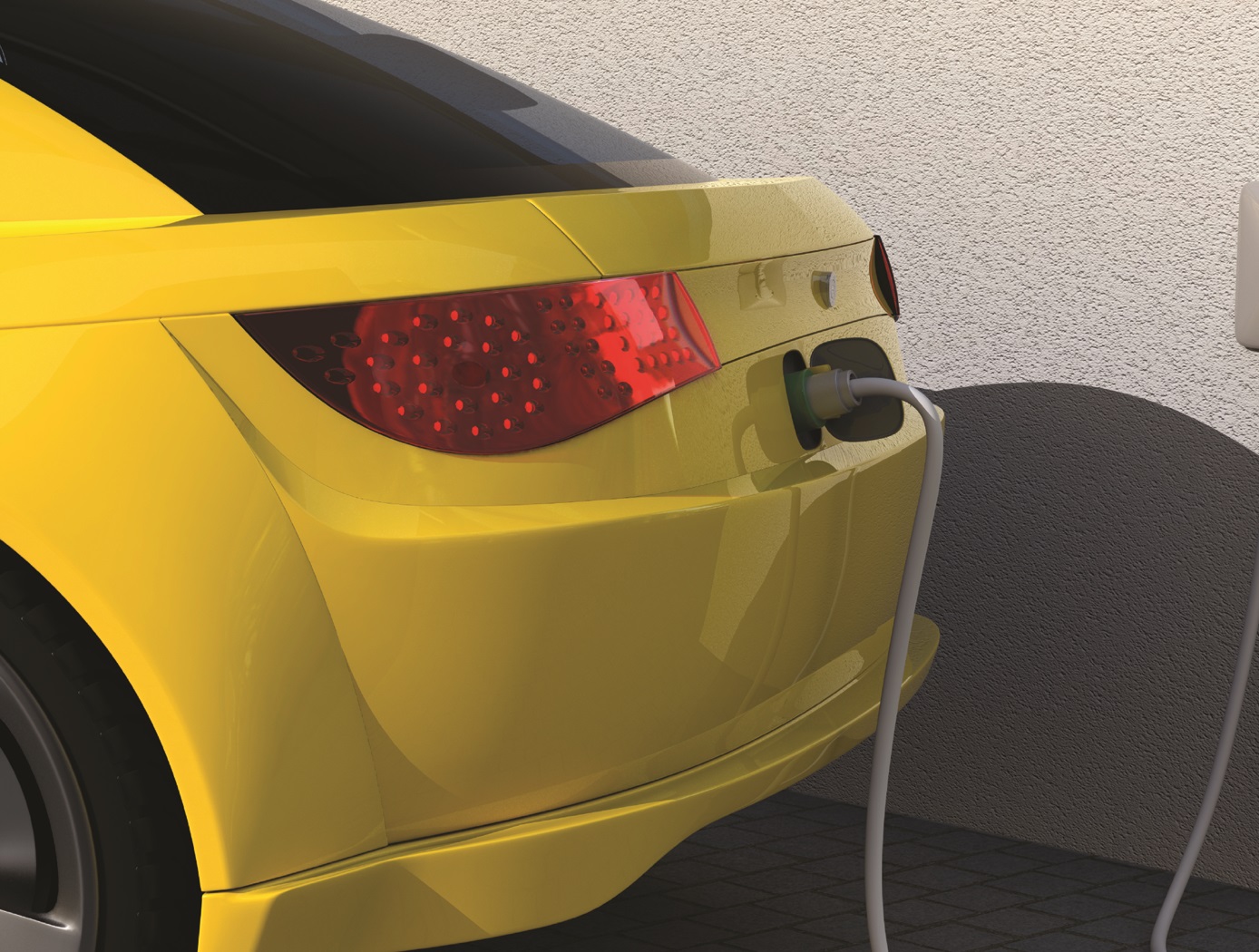
Battery Charge Equalizer System
The innovation consists of a transformer array connected to a battery array through rectification and filtering circuits. The transformer array is connected to a drive circuit and a timing and control circuit, which enables individual battery cells or cell banks to be charged. The timing and control circuit connects to a charge controller that uses battery instrumentation to determine which battery bank to charge. The system is ultra lightweight because it uses much fewer than one transformer per battery cell. For instance, 40 battery cells can be balanced with an array of just five transformers. The innovation can charge an individual cell bank at the same time while the main battery charger is charging the high-voltage battery system.
Conventional equalization techniques require complex and costly electrical circuitry to achieve cell monitoring and balancing. Further, such techniques waste the energy from the most charged cells through a dummy resistive load (regulator), which is inefficient and generates excess heat. In contrast, this system equalizes battery strings by selectively charging cells that need it. The technology maintains battery state-of-charge to improve battery life and performance. In addition, the technology provides a fail-safe operation and a novel built-in electrical isolation for the main charge circuit, further improving the safety of high-voltage Li-ion batteries.
materials and coatings
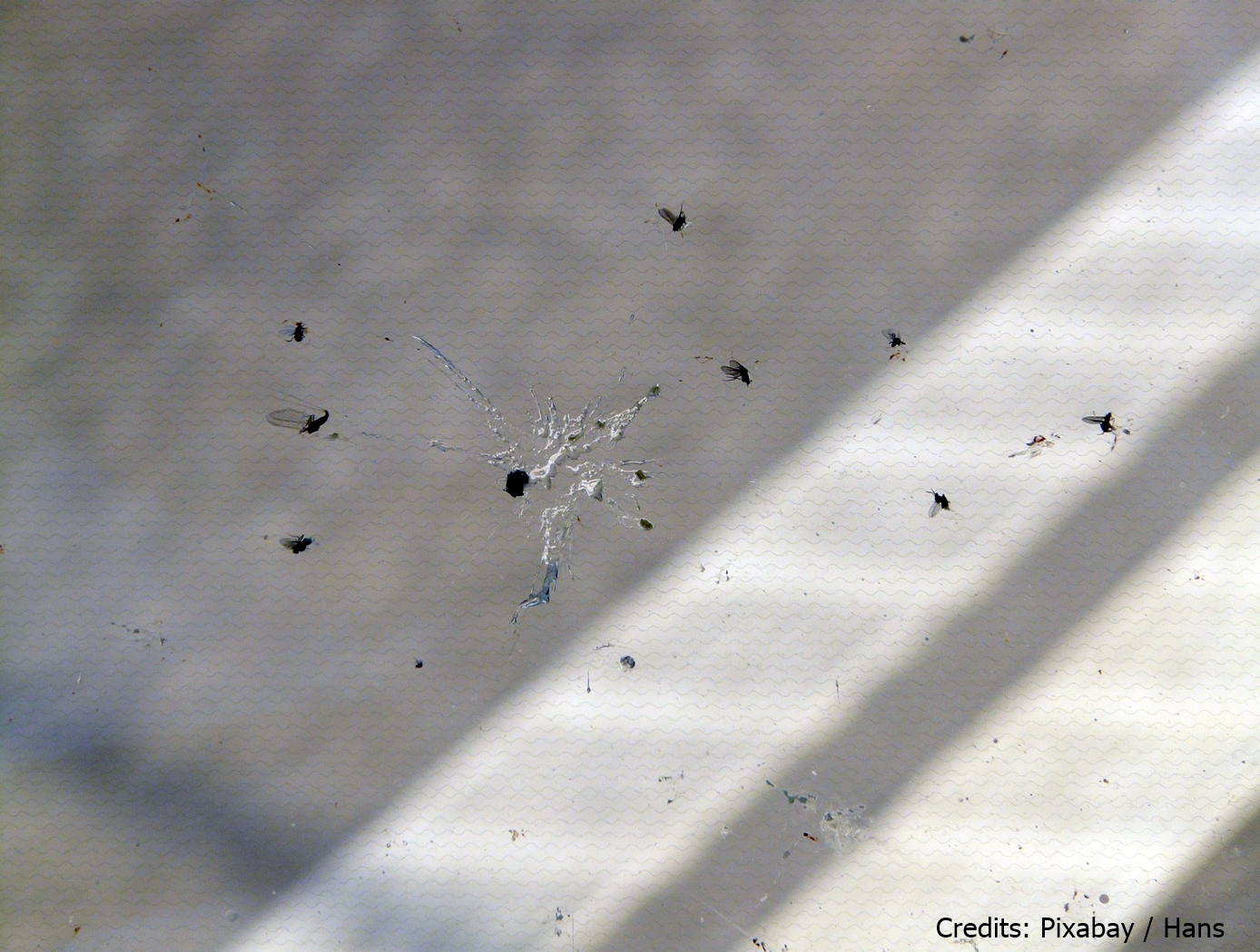
Hydrophobic Epoxy Coating for Insect Adhesion Mitigation
This technology is a copolymeric epoxy coating that is loaded with a fluorinated aliphatic chemical species and nano- to microscale particle fillers. The coating was developed as a hydrophobic and non-wetting coating for aerodynamic surfaces to prevent accumulation of insect strike remains that can lead to natural laminar flow disruption and aerodynamic inefficiencies. The coating achieves hydrophobicity in two ways. First, the fluorinated aliphatic chemical species are hydrophobic surface modification additives that preferentially migrate to the polymer surface that is exposed to air. Secondly, the incorporation of particle fillers produces a micro-textured surface that displays excellent resistance to wetting. Combined, these two factors increase hydrophobicity and can also be used to readily generate superhydrophobic surfaces.
mechanical and fluid systems

Compact Vibration Damper
Structural vibrations frequently need to be damped to prevent damage to a structure. To accomplish this, a standard linear damper or elastomeric-suspended masses are used. The problem associated with a linear damper is the space required for its construction. For example, if the damper's piston is capable of three inches of movement in either direction, the connecting shaft and cylinder each need to be six inches long. Assuming infinitesimally thin walls, connections, and piston head, the linear damper is at least 12 inches long to achieve +/-3 inches of movement. Typical components require 18+ inches of linear space. Further, tuning this type of damper typically involves fluid changes, which can be tedious and messy. Masses suspended by elastomeric connections enable even less range of motion than linear dampers.
The NASA invention is for a compact and easily tunable structural vibration damper. The damper includes a rigid base with a slider mass for linear movement. Springs coupled to the mass compress in response to the linear movement along either of two opposing directions. A rack-and-pinion gear coupled to the mass converts the linear movement to a corresponding rotational movement. A rotary damper coupled to the converter damps the rotational movement. To achieve +/- 3 inches of movement, this design requires slightly more than six inches of space.
materials and coatings
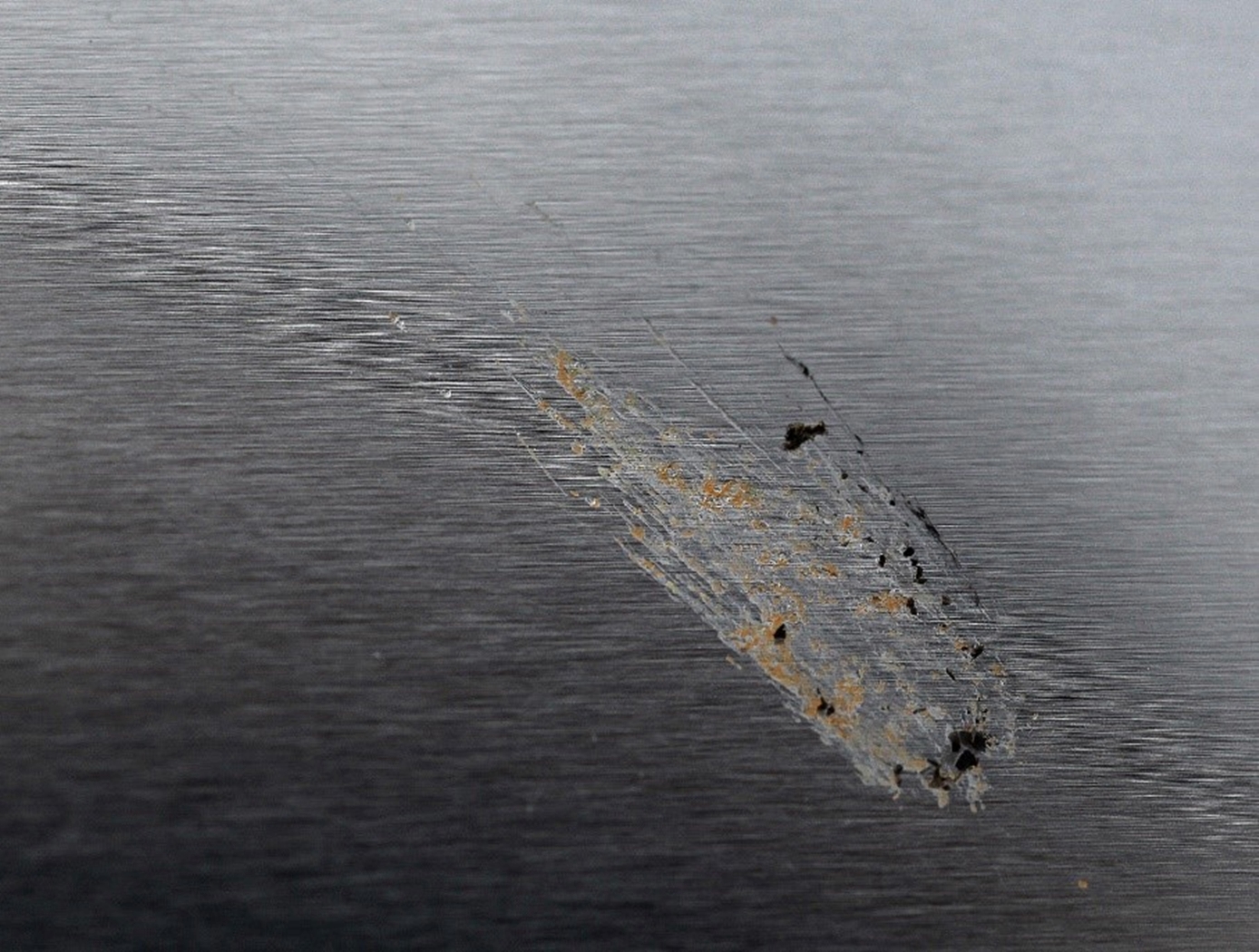
Chemical and Topographical Surface Modifications for Insect Adhesion Mitigation
The technology is a method of mitigating insect residue adhesion to various surfaces upon insect impact. The process involves topographical modification of the surface using laser ablation patterning followed by chemical modification or particulate inclusion in a polymeric matrix. Laser ablation patterning is performed by a commercially available laser system and the chemical spray deposition is composed of nanometer sized silica particles with a hydrophobic solution (e.g. heptadecafluoro-1,1,2,2-tetrahydrodecyltriethoxysilane) in an aqueous ethanol solution. Both topographic and chemical modification of the substrate is necessary to achieve the desired performance.
mechanical and fluid systems
Feedthrough for Severe Environments and Temperatures
Space and ground launch support related hardware often operate under extreme pressure, temperature, and corrosive conditions. When dealing with this type of equipment, it is frequently necessary to run wiring, tubes, or fibers through a barrier separating one process from another with one or both operating in extreme environments. Feedthroughs used to route the wiring, tubes, or fibers through these barriers must meet stringent sealing and leak tightness requirements.
This affordable NASA feedthrough meets or exceeds all sealing and leak requirements utilizing easy-to-assemble commercial-off-the-shelf hardware with no special tooling. The feedthrough is a fully reconfigurable design; however, it can also be produced as a permanent device. Thermal cycling and helium mass spectrometer leak testing under extreme conditions of full cryogenic temperatures and high vacuum have proven the sealing capability of this feedthrough with or without potting (epoxy fill) on the ends. Packing material disks used in the construction of the device can be replaced as needed for rebuilding a given feedthrough for another job or a different set of feeds if potting is not used for the original feedthrough build. (Potting on one or both sides of the sleeve provides double or triple leak sealing protection). Variable Compression Ratio (VCR) connectors were adapted for the pressure seal on the feedthrough; however, any commercial connector can be similarly adapted. The design can easily be scaled up to larger (2" diameter) and even very large (12" or more) sizes.

