Flexible Body Control Using Fiber Optic Sensors (FlexFOS)
sensors
Flexible Body Control Using Fiber Optic Sensors (FlexFOS) (KSC-TOPS-74)
Sensors provide three degrees of freedom real-time structural dynamics and flexible body information
Overview
NASA Kennedy Space Center seeks partners interested in the commercial application of the Flexible Body Control Using Fiber Optic Sensors (FlexFLOS) technology. The FlexFOS measures flexible dynamic state through a reference strain structure (RSS) combined with fiber optic strain sensors (FOSS). This new system for strain measurement provides users with an exponential increase in the amount of dynamic data, affording end users with a more precise and accurate assessment of critical structural dynamics. When combined with an inertial measurement sensor, FlexFOS enables end users to separate out the rigid body and flexible body components of the total motion. KSC is now seeking commercial partners for licensing or further development of this novel sensor system.
The Technology
Aerospace vehicles experience flexible dynamics that have adverse effects on guidance, navigation, and control. Vehicles that include automated control are further affected by flexible modes and structural vibrations. Flexible dynamics become even more critical as demand for larger and more fuel efficient vehicles increases.
Using fiber optic technology to collect both flexible and rigid body information enables increased knowledge (data) of the state of a vehicle, a more robust collection method against weather conditions, and a more cost-effective measurement method. This technology could potentially be applied to aerospace vehicles as well as commercial space structures, commercial aerospace structures, cranes, buildings, or bridges - anything with a large cross sectional ratio.
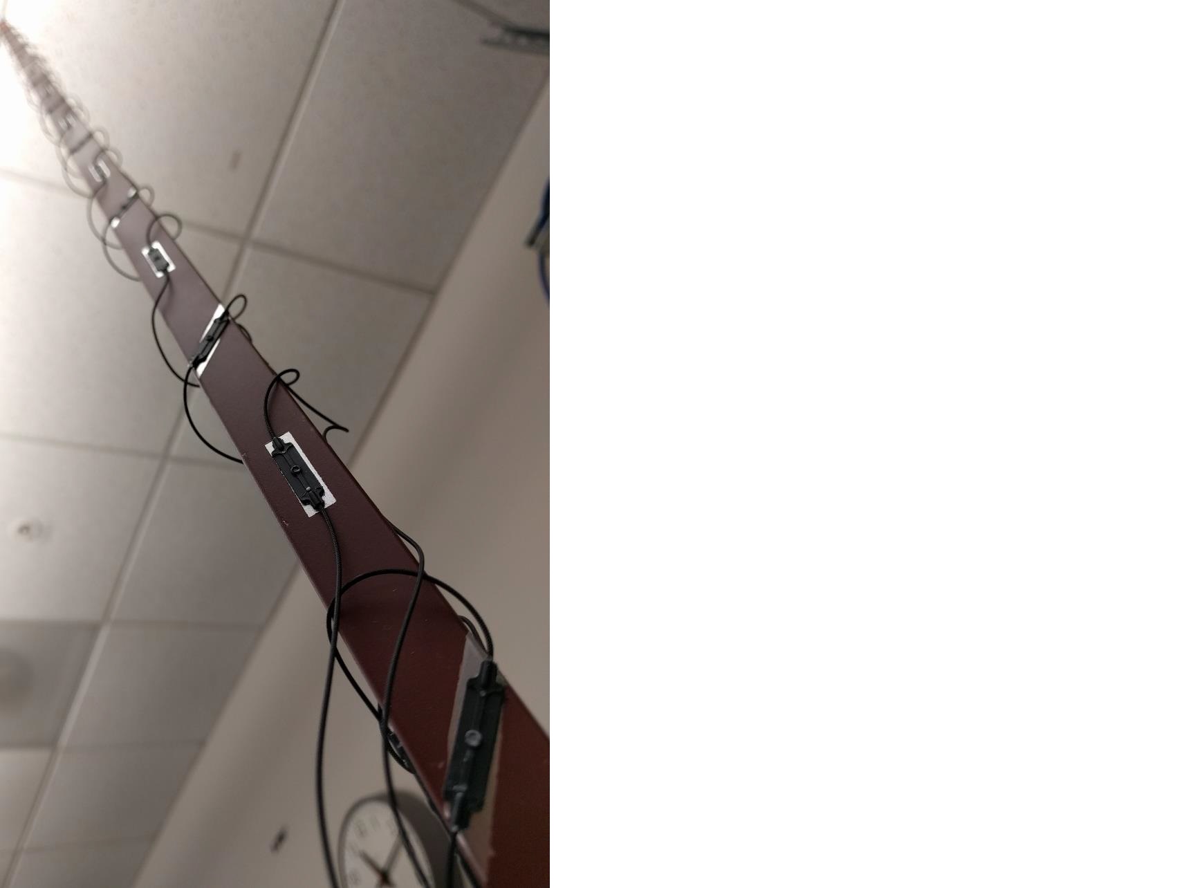
The RSS is the key to developing a sensor which provides flexible body kinematics. A reference structure must be chosen that minimizes weight impacts while retaining structural integrity. The reference structure material must also be very predictable and repeatable. Once this geometry has been optimized, analyzed, and mapped it is integrated with strain sensors making it a Reference Strain Structure. The RSS must then be integrated into an adaptive structure, which both protects and provides a connection to the desired structure to be measured.
The RSS combined with the properly designed algorithms provides the capability and portability to be installed on any of the aforementioned structures alleviating unique engineering and calibration required for each structure or vehicle. It also provides the capability to employ actuators to counteract the effects of structural vibrations. FlexFOS provides a simple, portable solution adaptable to any structure.


Benefits
- Real-Time Structural Shape Sensing
- Increased Control System Robustness
- Increased Flight Margin Resolution Across Multiple Disciplines
- Potential Elimination of Conventional Aerodynamic Control Surfaces
Applications
- Government and Commercial Aerospace Vehicles
- Government and Commercial Space Structures
- Cranes
- Buildings
- Bridges
- Wind Turbine Blades
Similar Results

Lightweight Fiber Optic Sensors for Real-Time Monitoring of Structural Health
How It Works
The FOSS technology employs efficient, real-time, data driven algorithms for interpreting strain data. The fiber Bragg grating sensors respond to strain due to stress or pressure on the substrate. The sensors feed these strain measurements into the systems algorithms to determine shape, stress, temperature, pressure, strength, and operational load in real time.
Why It Is Better
Conventional strain gauges are heavy, bulky, spaced at distant intervals (which leads to lower resolution imaging), and unable to provide real-time measurements. Armstrong's system is virtually weightless, and thousands of sensors can be placed at quarter-inch intervals along an optical fiber the size of a human hair. Because these sensors can be placed at such close intervals and in previously inaccessible regions (for example, within bolted joints, embedded in a composite structure), the high-resolution strain measurements are more precise than ever before. The fiber optic sensors are non-intrusive and easy to install—thousands of sensors can be installed in less time than conventional strain sensors and the system is capable of processing information at the unprecedented rate of 100 samples per second. This critical, real-time monitoring capability enables an immediate and informed response in the event of an emergency and allows for precise, controlled monitoring to help avoid such scenarios.
For more information about the full portfolio of FOSS technologies, see DRC-TOPS-37 or visit https://technology-afrc.ndc.nasa.gov/featurestory/fiber-optic-sensing

Shape Sensing Innovations Dramatically Improve Structural Design Tools
Armstrong's technologies provide a convenient way to calculate distributed deformed orientation angles—that is, roll, pitch, and yaw—as well as determine the deformed shape of an object in 3D space. Developed to facilitate monitoring and control of flexible aircraft designs when used in conjunction with Armstrong's multi-patented FOSS technology, these new tools improve shape-sensing accuracy for highly deformable structures such as bridges, wind turbines, robotic instruments, and much more. These tools also can be integrated into commercial fiber optic sensing systems.
How It Works
Researchers developed a technology that uses curved displacement transfer functions to determine 3D shape and calculate the operational load of a structure. It works by dividing the structure into multiple small domains, whose junctures match sensing stations, so that data is collected in a piecewise, nonlinear fashion. The innovation calculates structural stiffness (bending and torsion) and operational loads (bending moments, shear loads, and torques) in near real time.
The method tracks rotations and orientation by employing quaternion mathematical operations, a faster process than rotation matrices used in previous shape-sensing algorithms. The result is an algorithm that can track multiple angles—displacement, twist, and rotation—at the same time to enable curvilinear shaping sensing. Armstrong researchers have validated the method on the large-scale passive aeroelastic tailored (PAT) wing.
Why It Is Better
These new technologies advance the ability of fiber optic sensing systems to determine the shape and operational loads of nonlinear flexible surfaces. They can improve the structural integrity of a range of large structures—from buildings and bridges to ocean vessels and aircraft. These innovations reliably provide highly accurate critical information in real time, enabling corrective action to avert disasters.
For more information about the full portfolio of FOSS technologies, see DRC-TOPS-37 or visit https://technology-afrc.ndc.nasa.gov/featurestory/fiber-optic-sensing

Fiber Optic Sensing Technologies
The FOSS technology revolutionizes fiber optic sensing by using its innovative algorithms to calculate a range of useful parameters—any and all of which can be monitored simultaneously and in real time. FOSS also couples these cutting-edge algorithms with a high-speed, low-cost processing platform and interrogator to create a single, robust, stand-alone instrumentation system. The system distributes thousands of sensors in a vast network—much like the human body's nervous system—that provides valuable information.
How It Works
Fiber Bragg grating (FBG) sensors are embedded in an optical fiber at intervals as small as 0.25 inches, which is then attached to or integrated into the structure. An innovative, low-cost, temperature-tuned distributed feedback (DFB) laser with no moving parts interrogates the FBG sensors as they respond to changes in optical wavelength resulting from stress or pressure on the structure, sending the data to a processing system. Unique algorithms correlate optical response to displacement data, calculating the shape and movement of the optical fiber (and, by extension, the structure) in real time, without affecting the structure's intrinsic properties. The system uses these data to calculate additional parameters, displaying parameters such as 2D and 3D shape/position, temperature, liquid level, stiffness, strength, pressure, stress, and operational loads.
Why It Is Better
FOSS monitors strain, stresses, structural instabilities, temperature distributions, and a plethora of other engineering measurements in real time with a single instrumentation system weighing less than 10 pounds. FOSS can also discern between liquid and gas states in a tank or other container, providing accurate measurements at 0.25-inch intervals. Adaptive spatial resolution features enable faster signal processing and precision measurement only when and where it is needed, saving time and resources. As a result, FOSS lends itself well to long-term bandwidth-limited monitoring of structures that experience few variations but could be vulnerable as anomalies occur (e.g., a bridge stressed by strong wind gusts or an earthquake).
As a single example of the value FOSS can provide, consider oil and gas drilling applications. The FOSS technology could be incorporated into specialized drill heads to sense drill direction as well as temperature and pressure. Because FOSS accurately determines the drill shape, users can position the drill head exactly as needed. Temperature and pressure indicate the health of the drill. This type of strain and temperature monitoring could also be applied to sophisticated industrial bore scope usage in drilling and exploration.
For more information about the full portfolio of FOSS technologies, see visit https://technology-afrc.ndc.nasa.gov/featurestory/fiber-optic-sensing

Highly Accurate Position Detection and Shape Sensing with Fiber Optics
NASA's novel method was developed to more accurately measure the position and shape of optical fibers. Multi-core optical fibers contain multiple light-guiding cores arranged symmetrically. Sensors, such as FBGs, are embedded into each of the cores (Figure 1). Such an arrangement allows for the measurement of strain in each core of the fiber at specific axial locations along the fiber. When a multi-core fiber is subjected to bending, the strain imposed in each core relative to one another is used to provide position information (Figure 2).
In the past, shape-sensing measurements using optical fibers estimated bending at sequential points along the fiber, and the resulting measurement had many discontinuities and errors. The combination of these errors resulted in a very poor indication of actual fiber position in three-dimensional space. NASA's patent-pending algorithms and apparatus incorporate not only fiber bending measurements, but fiber twisting measurements as well, to eliminate previous sources of error. The uniqueness of the algorithm is in how the curvature, bend-direction, and twisting information of the fiber are all brought together to obtain a highly accurate 3-D location and shape characterization. The new methods have been demonstrated to significantly improve the accuracy of multi-core fiber optic shape sensors.

Cord Tension Measurement Device (C-Gauge)
The C-Gauge is made of a 3D-printed aluminum body with strain gauges attached to the inner and outer walls of the connecting beam. The legs of the gauge attach firmly to the cord. When the cord is stretched, the tension in the cord goes through the legs and into the beam, causing it to bend. This bending creates a tension and compression stress in the bottom and top surface of the beam, respectively. The strain gauges capture the tension and compression, which are then used to determine the tension in the cord. The use of multiple strain gauges mitigates any torsion loading of the gauge and provides a direct measurement of the axial tension load of the cord.
The C-Gauge is a low-profile, non-invasive system that can be installed onto an existing cord in a system (e.g., the suspension, reefing, or riser lines in a parachute) without the need to remove or re-install the cord. It is small and lightweight and does not add stiffness or weight to the cord and thus does not affect the dynamics of the parachute or the structural response of the system. The C-Gauge can be scaled to larger and smaller sizes to measure larger and smaller load capabilities, dependent on the cord.
The C-Gauge is at a TRL 4 (component and/or breadboard validation in a laboratory environment) and it is now available for your company to license and develop into a commercial product. Please note that NASA does not manufacture products itself for commercial sale.


