Novel Radiation Shielding Material for Dramatically Extending the Orbit Life of Cubesats
Materials and Coatings
Novel Radiation Shielding Material for Dramatically Extending the Orbit Life of Cubesats (LAR-TOPS-250)
Z grade material for lightweight radiation shielding
Overview
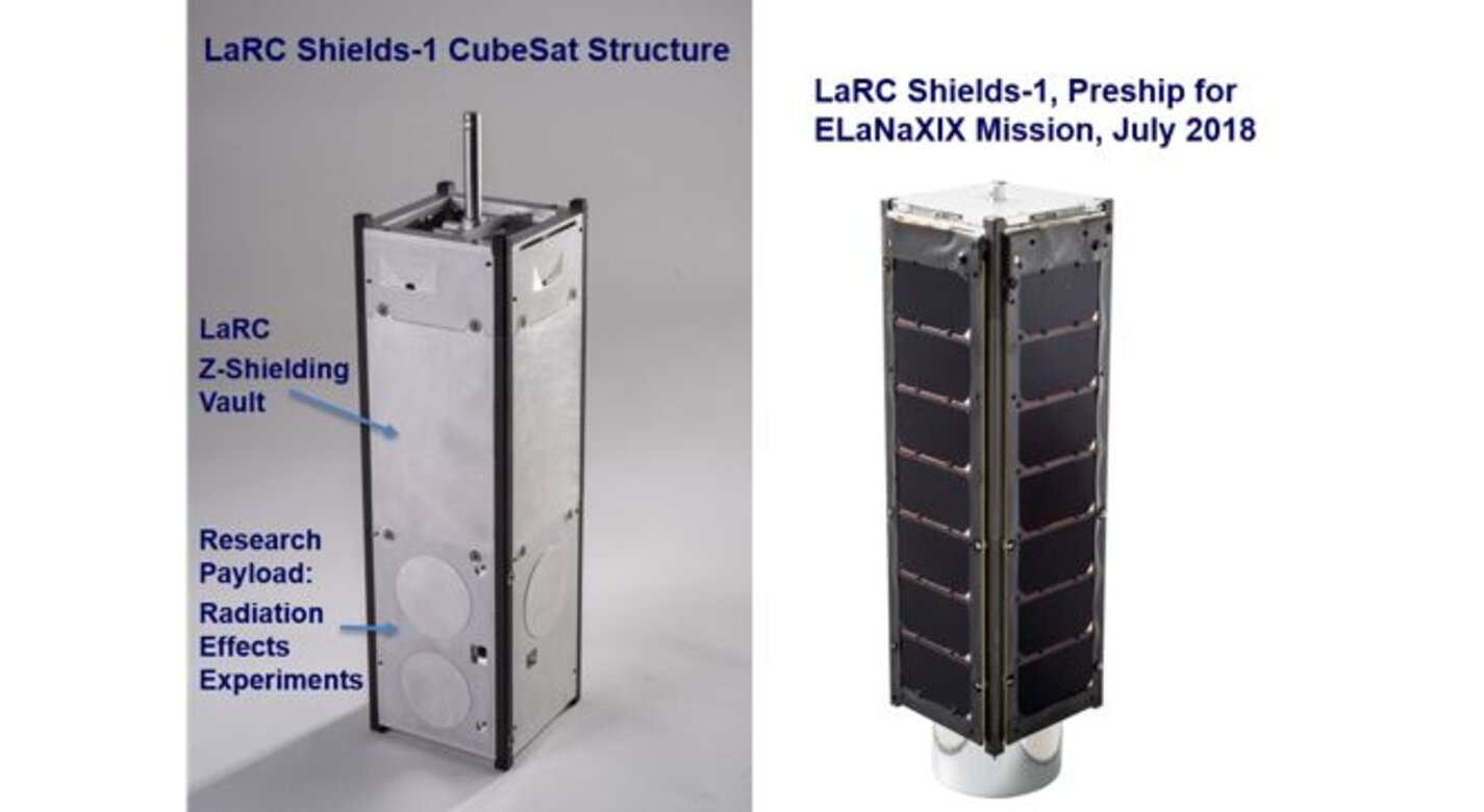
The NASA Langley Research Center has developed an innovative radiation shield made by layering metal materials in the Z-shielding method. It is a new, low cost and easy to implement method to protect CubeSat electronic circuits from ionizing radiation found in Low Earth Orbits. It is estimated that this approach can extend the life of CubeSat electronics by an order of magnitude.
The Technology
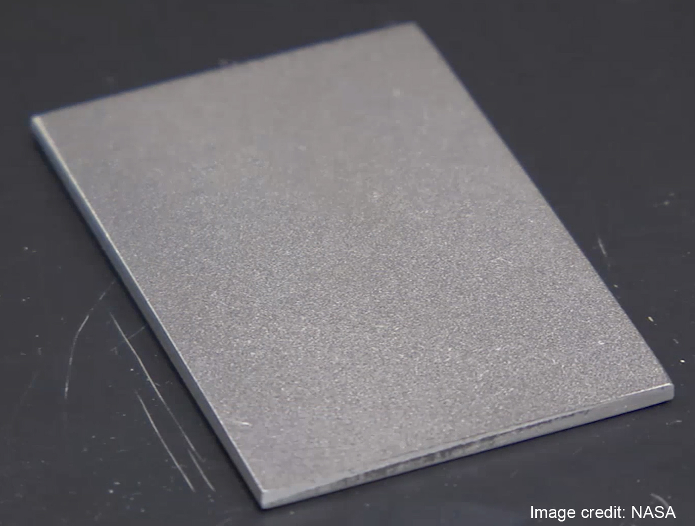
A high density metal, such as tantalum or tungsten is coated onto thin aluminum sheet in precise ratios and thicknesses. The combined sheet is then easily formed into standardized enclosures compatible with CubeSat design and performance specifications.


Benefits
- Extends the effective life of typical CubeSat missions from 3 months to years
- An 18x reduction of total ionizing dose and removal of internal charging effects
- Increases return on investment made in CubeSat missions. They currently fail prior to orbital decay due to radiation damage
- The vaults and material are compatible with CubeSat dimensions and the CubeSat dispensers
Applications
- Cubesats and Smallsats where longer functional orbit life is desired
- Medical Imagers where lighter weight shielding is desired
Technology Details
Materials and Coatings
LAR-TOPS-250
LAR-19109-1
LAR-19109-1-CON
LAR-19109-2-CON
LAR-18586-1-CON
LAR-18586-2-CON
Thomsen, Laurence.et. al. NASA's State of the Art Small Spacecraft Technology, 2021. Section 6.5 Radiation Effects and Mitigation Strategies (https://www.nasa.gov/smallsat-institute/sst-soa/structures-materials-and-mechanisms#6.5)
Similar Results

Atomic Number (Z)-Grade Radiation Shields from Fiber Metal Laminates
This technology is a flexible, lighter weight radiation shield made from hybrid carbon/metal fabric and based on the Z-grading method of layering metal materials of differing atomic numbers to provide radiation protection for protons, electrons, and x-rays. To create this material, a high density metal is plasma spray-coated to carbon fiber. Another metal with less density is then plasma spray-coated, followed by another, and so on, until the material with the appropriate shielding properties is formed. Resins can be added to the material to provide structural adhesion, reducing the need for mechanical bonding. This material is amenable to molding and could be used to build custom radiation shielding to protect cabling and electronics in situations where traditional metal shielding is difficult to place.

High Atomic Number Coatings for Fabrics
High atomic number materials, such as tantalum, do not bond well to oxygen- and hydroxyl-rich surfaces, such as glass fibers. These metals often form surface oxides when layered on glass fabric, resulting in flaking of the high atomic number material off the fabric during cutting, folding, and/or handling.
To improve coating durability, this invention applies a lower atomic number metal as a tie down layer first before applying the high atomic number metal layer. The tie down layer reduces oxide formation between the substrate and the high atomic number material, promoting adhesion. Titanium has shown strong adhesion with different metals and is effective at reducing oxide formation when diffusion bonded to itself or other materials. It has been shown to be effective at improving durability when thermally sprayed onto a glass fiber fabric as a tie down layer for a subsequent tantalum layer (also applied via RF plasma spray). The titanium layer is only approximately 1 mil thick but results in strong adhesion of the tantalum layer by inter-metallic or diffusion bonding. A thermal spray process may be used, as well.
This innovation enables the delivery of high atomic metal coating on glass fiber fabrics and other polymeric substrates that are lower cost, lighter weight, and durable to form a flexible cloth material with Z-graded radiation shielding. Coated samples have been produced and the technology is currently at a technology readiness level (TRL) of 4 (prototype).

Silicon Oxide Coated Aluminized Polyimide Film Radiator Coating
The SiOx Coated Aluminized Polyimide Film Radiator Coating uses all the exposed surfaces on the six sides of a CubeSat as radiators. All the internal components are thermally coupled to the radiators. Waste heat from the internal components is transferred by conduction to the radiators through its aluminum structure or frame. SiOx thin film coated aluminized polyimide film is used as the radiator coating. Its total thickness is approximately 0.05 mm, which is predominately the polyimide film thickness. Polyimide film is known commercially as Kapton. The coating is bonded to the CubeSat exterior by using an acrylic transfer adhesive.
SiOx Coated Aluminized Polyimide Film Radiator Coatings absorptance and emittance can be tailored to meet the component thermal requirements by altering the SiOx thickness. Since the SiOx is a thin film, altering its thickness has no significant effect on the total thickness of the radiator coating. An indium tin oxide (ITO) thin film can be added to make the coating conductive, if needed, without affecting the absorptance or emittance. This coating, with or without ITO, can be used for various CubeSat applications. By tailoring the absorptance and emittance of this coating, external MLI blankets and active heater control are eliminated. The thermal connection between heat generating components and the battery eliminates the need for a battery heater.

Novel Antenna Concept for CubeSat Platforms
The side walls and railing rods of a CubeSat are replaced by RF radiators that double as supporting structures. The RF radiators are hollow railing rods with inner dimensions that function as a waveguide to carry RF energy at a desired frequency. Radiating slots are cut on two of the four sides of hollow tubes tube that are open to outside environment. Different operating frequency antennas may be placed at each of the Cubesats four corners. Thus the railing rods provide RF antenna functionality in addition to structurally supporting the CubeSat structure.
While this technology was designed for Cubesats, it may be utilized in any technology that utilizes a structural frame. The advantages of this system are increased reliability due to the elimination of deployment mechanisms and decreased payloads. Higher frequency
antennas with increased gain and directivity may be embedded into the rails. These higher frequencies are especially useful for remote sensing.

A Broadband, Compact Low-Power microwave Radiometer Down Converter for Small Satellite Applications
The system includes a fundamental local oscillator (LO) source composed of a broad-band tunable frequency synthesizer as well as a crystal oscillator. The synthesizer employs a harmonic doubler to expand frequency coverage. The CubeRRT system uses a series of RF switches and band-pass filters, to select the desired harmonic while suppressing unwanted harmonics. The CubeRRT system uniquely combines several technologies to minimize the number of frequency banks and thus reduce mass, volume and power requirements. The CubeRRT system uses four frequency banks in order to provide continuous microwave receiver coverage from 6GHz to 40GHz.


