Guided wave-based system for cure monitoring of composites using piezoelectric discs and fiber Bragg gratings (FBGs)
Sensors
Guided wave-based system for cure monitoring of composites using piezoelectric discs and fiber Bragg gratings (FBGs) (LAR-TOPS-303)
Use of fiber optic sensors to measure guided waves as a cure monitoring system
Overview
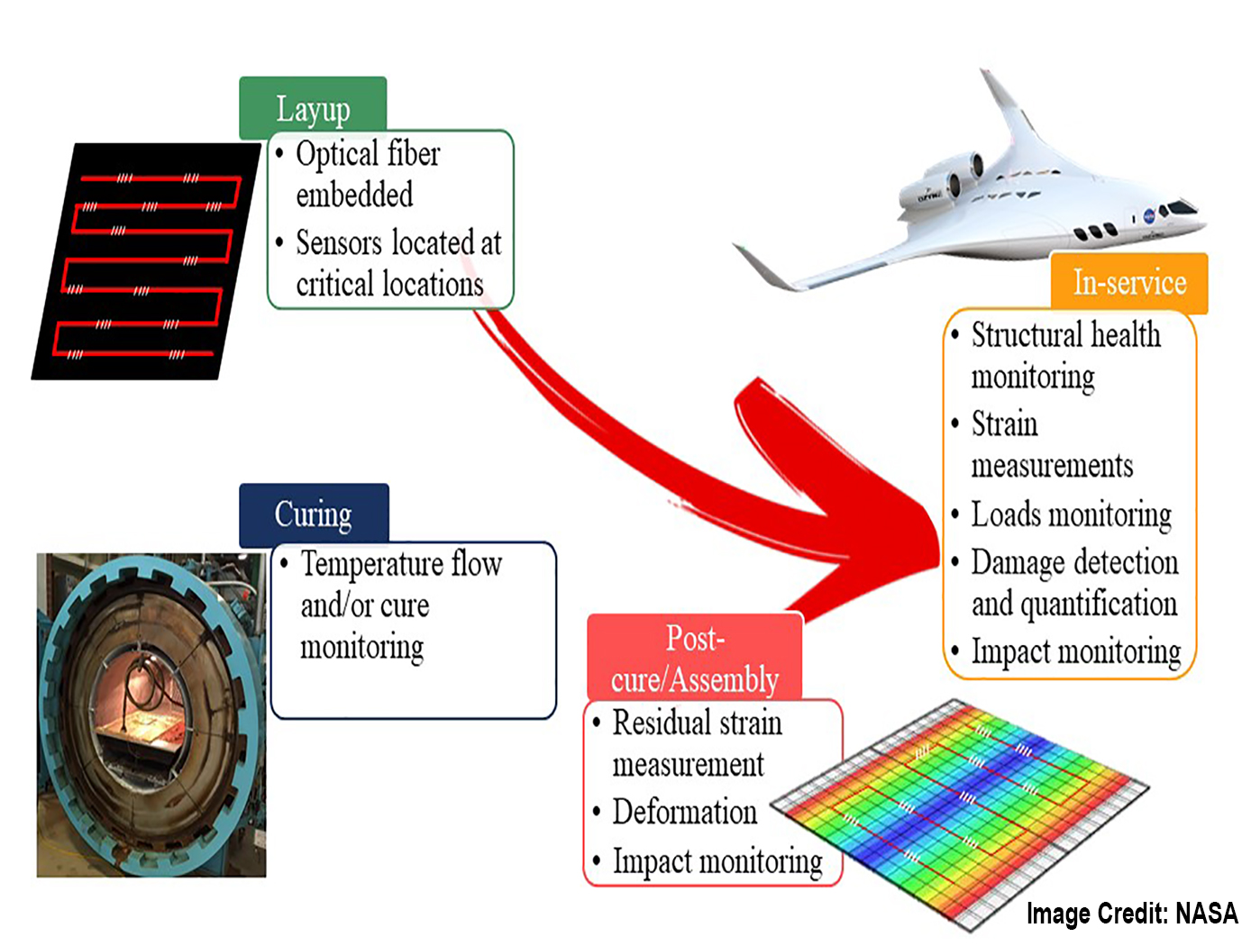
The use of carbon fiber reinforced polymer composites for structural components in aircraft, automotive and other applications has grown rapidly and is in extensive use today. A prime example is the Boeing 787 Dreamliner of which the entire fuselage and wings are constructed from CRFP's. Consequently, as a quality control measure, means to monitor the cure rate of the resins as well as means to detect defects has become critically important. Inventors at NASA Langley have developed and demonstrated a system using fiber optic sensors to measure guided waves that propagate in a part as a cure monitoring system. Life-cycle monitoring is now possible because of optical fiber embedded in composite during cure.
The Technology
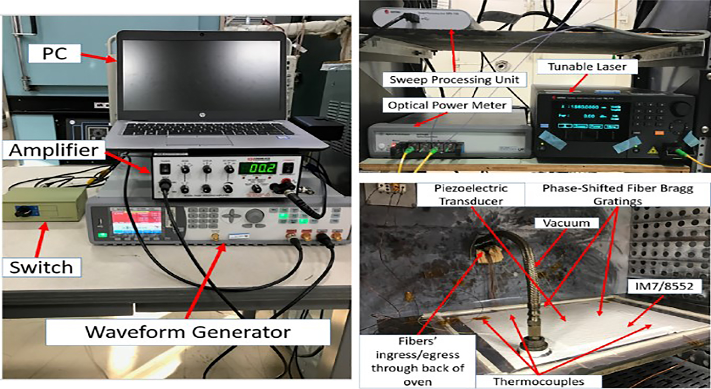
This system connects the properties of the guided waves to the phase changes of a composite part. The system measures temperature, strain, and guided waves during cure almost simultaneously. During life-cycle monitoring, it is feasible to use embedded fiber optic sensors for both load monitoring because of the ability to measure strain and damage detection because of the ability to record ultrasonic guided waves. The guided wave system is incorporated directly into standard curing equipment and technique. It has also been tested and works with flat panels as well as complex structures. The technology would be valuable to manufacturers of aircraft parts (fuselage, wing and other sections), marine hull sections, high speed rail sections, automotive parts and perhaps even building parts. One major application that exists presently, is the fabrication of fuselage and wing sections for aircraft where carbon fiber composite sections are used such as Boeing's 787 Dreamliner.


Benefits
- Defect detection during cure
- In-situ measurements during all phases (liquid, rubbery, and glassy)
- Embedded sensors
- Performs strain based cure monitoring
- Life-cycle monitoring of aircraft/other critical structures during service
- Can perform low frequency strain (load monitoring) based cure monitoring and high frequency guided wave sensing (damage detection) almost simultaneously during cure
Applications
- General aviation
- Automotive
- Marine
- High speed rail
- Wind turbines
Similar Results

System for In-situ Defect Detection in Composites During Cure
NASA's System for In-situ Defect (e.g., porosity, fiber waviness) Detection in Composites During Cure consists of an ultrasonic portable automated C-Scan system with an attached ultrasonic contact probe. This scanner is placed inside of an insulated vessel that protects the temperature-sensitive components of the scanner. A liquid nitrogen cooling systems keeps the interior of the vessel below 38°C. A motorized X-Y raster scanner is mounted inside an unsealed cooling container made of porous insulation boards with a cantilever scanning arm protruding out of the cooling container through a slot. The cooling container that houses the X-Y raster scanner is periodically cooled using a liquid nitrogen (LN2) delivery system. Flexible bellows in the slot opening of the box minimize heat transfer between the box and the external autoclave environment. The box and scanning arm are located on a precision cast tool plate. A thin layer of ultrasonic couplant is placed between the transducer and the tool plate. The composite parts are vacuum bagged on the other side of the tool plate and inspected. The scanning system inside of the vessel is connected to the controller outside of the autoclave. The system can provide A-scan, B-scan, and C-scan images of the composite panel at multiple times during the cure process.
The in-situ system provides higher resolution data to find, characterize, and track defects during cure better than other cure monitoring techniques. In addition, this system also shows the through-thickness location of any composite manufacturing defects during cure with real-time localization and tracking. This has been demonstrated for both intentionally introduced porosity (i.e., trapped during layup) as well processing induced porosity (e.g., resulting from uneven pressure distribution on a part). The technology can be used as a non-destructive evaluation system when making composite parts in in an oven or an autoclave, including thermosets, thermoplastics, composite laminates, high-temperature resins, and ceramics.

Calibration System for Automated Fiber Placement
NASA's new calibration system is a proprietary method to quickly design and make predictable and repeatable gap-and-overlap defects when employing AFP. The system creates defects within the course of layup with known sizes, geometries, and locations. Using this defect-creation technique, one can now accurately quantify the ability to detect defects on inspection systems, perform accurate risk assessments, and calibrate in-situ inspection equipment to specific materials. The equipment that makes the defects can be efficiently and inexpensively 3D printed. This technique is currently being used to successfully calibrate NASA's in situ inspection system for their AFP equipment.
AFP is experiencing increasing adoption in aerospace, automotive, and other industries that leverage large-scale advanced composite components. NASA's new AFP calibration system could be very useful to companies that develop and manufacture AFP machines or AFP machine inspection equipment to improve the quality of their products in a provable manner. Furthermore, users of AFP machines may find value in the tool for creating their own calibration standards.

Enhanced Fabrication Improves Temperature Sensing in Cryogenic Humid Environments
This technology was developed to improve Armstrong's multi-patented FOSS system, which has long been used to measure temperature and liquid levels in cryogenic environments. When the sensing system's fibers trapped humidity from the surrounding environment before their submersion into cryogenic liquids, the moisture adversely affected outputs. A new manufacturing process solves this problem, increasing reliability and accuracy not only of NASA's FOSS but also any fiber optic sensing system.
How It Works
Armstrong has developed a two-step process to assemble the sensors. First, the bare sensor fiber is inserted into an oven to expel all moisture from the fiber coating. Then, the moisture-free fiber is placed inside a humidity-controlled glove box to prevent it from absorbing any new moisture. While inside the glove box, the fiber is inserted into a loose barrier tubing that isolates the fiber yet is still thin enough to provide adequate thermal transfer. The tubing can be further purged with various gases while it is inside the glove box to provide additional moisture isolation.
This innovation is particularly useful for fiber optic systems that measure temperature and that identify any temperature stratifications within cryogenic liquids.
Why It Is Better
This process seals sensor fibers from environmental moisture, enabling fiber optic sensing systems to operate reliably in humid environments. The innovation eliminates erroneous readings that can occur due to moisture collection on the fiber sensors.
For more information about the full portfolio of FOSS technologies, see DRC-TOPS-37 or visit https://technology-afrc.ndc.nasa.gov/featurestory/fiber-optic-sensing

Fiber Optic Sensing Technologies
The FOSS technology revolutionizes fiber optic sensing by using its innovative algorithms to calculate a range of useful parameters—any and all of which can be monitored simultaneously and in real time. FOSS also couples these cutting-edge algorithms with a high-speed, low-cost processing platform and interrogator to create a single, robust, stand-alone instrumentation system. The system distributes thousands of sensors in a vast network—much like the human body's nervous system—that provides valuable information.
How It Works
Fiber Bragg grating (FBG) sensors are embedded in an optical fiber at intervals as small as 0.25 inches, which is then attached to or integrated into the structure. An innovative, low-cost, temperature-tuned distributed feedback (DFB) laser with no moving parts interrogates the FBG sensors as they respond to changes in optical wavelength resulting from stress or pressure on the structure, sending the data to a processing system. Unique algorithms correlate optical response to displacement data, calculating the shape and movement of the optical fiber (and, by extension, the structure) in real time, without affecting the structure's intrinsic properties. The system uses these data to calculate additional parameters, displaying parameters such as 2D and 3D shape/position, temperature, liquid level, stiffness, strength, pressure, stress, and operational loads.
Why It Is Better
FOSS monitors strain, stresses, structural instabilities, temperature distributions, and a plethora of other engineering measurements in real time with a single instrumentation system weighing less than 10 pounds. FOSS can also discern between liquid and gas states in a tank or other container, providing accurate measurements at 0.25-inch intervals. Adaptive spatial resolution features enable faster signal processing and precision measurement only when and where it is needed, saving time and resources. As a result, FOSS lends itself well to long-term bandwidth-limited monitoring of structures that experience few variations but could be vulnerable as anomalies occur (e.g., a bridge stressed by strong wind gusts or an earthquake).
As a single example of the value FOSS can provide, consider oil and gas drilling applications. The FOSS technology could be incorporated into specialized drill heads to sense drill direction as well as temperature and pressure. Because FOSS accurately determines the drill shape, users can position the drill head exactly as needed. Temperature and pressure indicate the health of the drill. This type of strain and temperature monitoring could also be applied to sophisticated industrial bore scope usage in drilling and exploration.
For more information about the full portfolio of FOSS technologies, see visit https://technology-afrc.ndc.nasa.gov/featurestory/fiber-optic-sensing

Lightweight Fiber Optic Sensors for Real-Time Monitoring of Structural Health
How It Works
The FOSS technology employs efficient, real-time, data driven algorithms for interpreting strain data. The fiber Bragg grating sensors respond to strain due to stress or pressure on the substrate. The sensors feed these strain measurements into the systems algorithms to determine shape, stress, temperature, pressure, strength, and operational load in real time.
Why It Is Better
Conventional strain gauges are heavy, bulky, spaced at distant intervals (which leads to lower resolution imaging), and unable to provide real-time measurements. Armstrong's system is virtually weightless, and thousands of sensors can be placed at quarter-inch intervals along an optical fiber the size of a human hair. Because these sensors can be placed at such close intervals and in previously inaccessible regions (for example, within bolted joints, embedded in a composite structure), the high-resolution strain measurements are more precise than ever before. The fiber optic sensors are non-intrusive and easy to install—thousands of sensors can be installed in less time than conventional strain sensors and the system is capable of processing information at the unprecedented rate of 100 samples per second. This critical, real-time monitoring capability enables an immediate and informed response in the event of an emergency and allows for precise, controlled monitoring to help avoid such scenarios.
For more information about the full portfolio of FOSS technologies, see DRC-TOPS-37 or visit https://technology-afrc.ndc.nasa.gov/featurestory/fiber-optic-sensing


