Plenoptic Camera
optics
Plenoptic Camera (LAR-TOPS-318)
Multi-spectral imaging for metrology using plenoptic camera technology
Overview
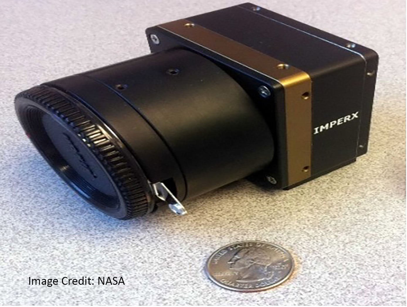
NASA's Langley Research Center has developed a plenoptic camera that can image two-dimensional (or in some cases three dimensional) spatial information as well as color, where in the final image each pixel contains a spectrum of the imaged scene. Plenoptic technology measures image brightness as well as the direction of the light rays. This enables new imaging capabilities, such as refocusing the acquired image to different depths and viewing the same scene from slightly different perspectives. As an imaging pyrometer, the camera can measure 2D temperature (and possibly emissivity) distributions.
The Technology
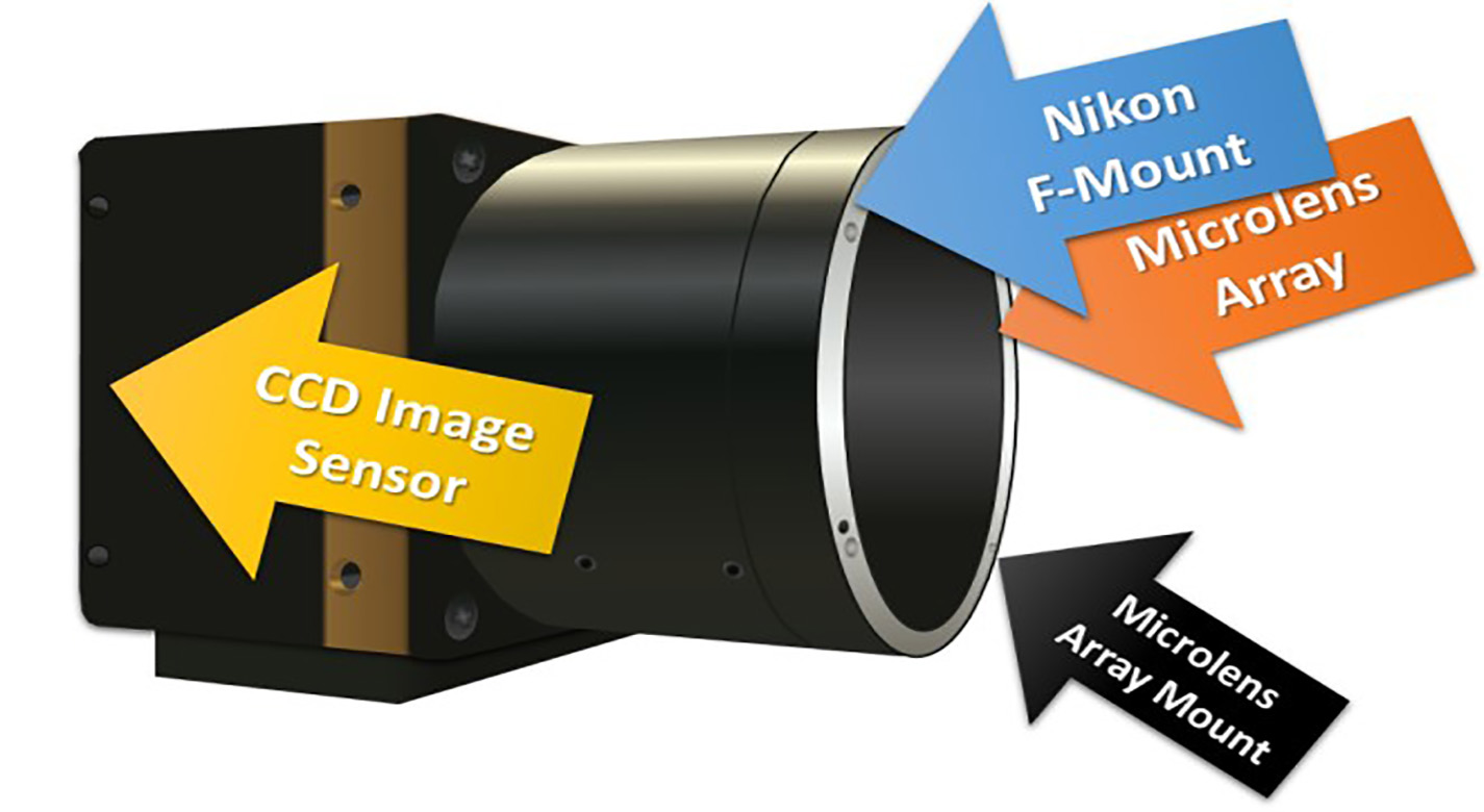
This camera incorporates an array of 470 x 360 microlenses, with each microlens producing an image onto a 14 x 14 pixel array. Specific colors or spectra can be continuous or arbitrarily determined; and can be easily and inexpensively modified. Modifications of the collected spectra can be useful for different applications where the emitted light needs to be analyzed to determine qualitative or quantitative information about a flow, object, or scene. The sensor can measure fluid, mechanical, thermodynamic, or structural properties of gases, liquids, and solids.


Benefits
- Inexpensive to produce
- Very easy to modify the filter arrangement to obtain different spectra
- Versatile -- the camera can be used for one application, and with a quick change of filter used for a completely different application
Applications
- Imaging pyrometer
- Emission spectroscopy imaging
- Smokestack pollution detection
- Flow temperature sensing
- Tomographic particle image velocimetry
- Astronomy / solar observations
Similar Results

Multi-Spectral Imaging Pyrometer
This NASA technology transforms a conventional infrared (IR) imaging system into a multi-wavelength imaging pyrometer using a tunable optical filter. The actively tunable optical filter is based on an exotic phase-change material (PCM) which exhibits a large reversible refractive index shift through an applied energetic stimulus. This change is non-volatile, and no additional energy is required to maintain its state once set. The filter is placed between the scene and the imaging sensor and switched between user selected center-wavelengths to create a series of single-wavelength, monochromatic, two-dimensional images. At the pixel level, the intensity values of these monochromatic images represent the wavelength-dependent, blackbody energy emitted by the object due to its temperature. Ratioing the measured spectral irradiance for each wavelength yields emissivity-independent temperature data at each pixel. The filter’s Center Wavelength (CWL) and Full Width Half Maximum (FWHM), which are related to the quality factor (Q) of the filter, are actively tunable on the order of nanoseconds-microseconds (GHz-MHz). This behavior is electronically controlled and can be operated time-sequentially (on a nanosecond time scale) in the control electronics, a capability not possible with conventional optical filtering technologies.

Computational Visual Servo
The innovation improves upon the performance of passive automatic enhancement of digital images. Specifically, the image enhancement process is improved in terms of resulting contrast, lightness, and sharpness over the prior art of automatic processing methods. The innovation brings the technique of active measurement and control to bear upon the basic problem of enhancing the digital image by defining absolute measures of visual contrast, lightness, and sharpness. This is accomplished by automatically applying the type and degree of enhancement needed based on automated image analysis.
The foundation of the processing scheme is the flow of digital images through a feedback loop whose stages include visual measurement computation and servo-controlled enhancement effect. The cycle is repeated until the servo achieves acceptable scores for the visual measures or reaches a decision that it has enhanced as much as is possible or advantageous. The servo-control will bypass images that it determines need no enhancement.
The system determines experimentally how much absolute degrees of sharpening can be applied before encountering detrimental sharpening artifacts. The latter decisions are stop decisions that are controlled by further contrast or light enhancement, producing unacceptable levels of saturation, signal clipping, and sharpness.
The invention was developed to provide completely new capabilities for exceeding pilot visual performance by clarifying turbid, low-light level, and extremely hazy images automatically for pilot view on heads-up or heads-down display during critical flight maneuvers.

Reflection-Reducing Imaging System for Machine Vision Applications
NASAs imaging system is comprised of a small CMOS camera fitted with a C-mount lens affixed to a 3D-printed mount. Light from the high-intensity LED is passed through a lens that both diffuses and collimates the LED output, and this light is coupled onto the cameras optical axis using a 50:50 beam-splitting prism.
Use of the collimating/diffusing lens to condition the LED output provides for an illumination source that is of similar diameter to the cameras imaging lens. This is the feature that reduces or eliminates shadows that would otherwise be projected onto the subject plane as a result of refractive index variations in the imaged volume. By coupling the light from the LED unit onto the cameras optical axis, reflections from windows which are often present in wind tunnel facilities to allow for direct views of a test section can be minimized or eliminated when the camera is placed at a small angle of incidence relative to the windows surface. This effect is demonstrated in the image on the bottom left of the page.
Eight imaging systems were fabricated and used for capturing background oriented schlieren (BOS) measurements of flow from a heat gun in the 11-by-11-foot test section of the NASA Ames Unitary Plan Wind Tunnel (see test setup on right). Two additional camera systems (not pictured) captured photogrammetry measurements.

Projected Background-Oriented Schlieren Imaging
The Projected BOS imaging system developed at the NASA Langley Research Center provides a significant advancement over other BOS flow visualization techniques. Specifically, the present BOS imaging method removes the need for a physically patterned retroreflective background within the flow of interest and is therefore insensitive to the changing conditions due to the flow. For example, in a wind tunnel used for aerodynamics testing, there are vibrations and temperature changes that can affect the entire tunnel and anything inside it. Any patterned background within the wind tunnel will be subject to these changing conditions and those effects must be accounted for in the post-processing of the BOS image. This post-processing is not necessary in the Projected BOS process here.
In the Projected BOS system, a pattern is projected onto a retroreflective background across the flow of interest (Figure 1). The imaged pattern in this configuration can be made physically (a pattern on a transparent slide) or can be digitally produced on an LCD screen. In this projection scheme, a reference image can be taken at the same time as the signal image, facilitating real-time BOS imaging and the pattern to be changed or optimized during the measurements. Thus far, the Projected BOS imaging technology has been proven to work by visualizing the air flow out of a compressed air canister taken with this new system (Figure 2).

Super Resolution 3D Flash LIDAR
This suite of technologies includes a method, algorithms, and computer processing techniques to provide for image photometric correction and resolution enhancement at video rates (30 frames per second). This 3D (2D spatial and range) resolution enhancement uses the spatial and range information contained in each image frame, in conjunction with a sequence of overlapping or persistent images, to simultaneously enhance the spatial resolution and range and photometric accuracies. In other words, the technologies allows for generating an elevation (3D) map of a targeted area (e.g., terrain) with much enhanced resolution by blending consecutive camera image frames. The degree of image resolution enhancement increases with the number of acquired frames.


