Digital Projection Focusing Schlieren System
instrumentation
Digital Projection Focusing Schlieren System (LAR-TOPS-349)
LCD-integrated optical assembly for image-based flow visualization
Overview
Researchers at NASA have developed a compact LCD-integrated optical assembly that enables a research camera to (simultaneously) collect focusing schlieren and other image-based measurement data (e.g., particle tracking velocimetry (PTV), particle imaging velocimetry (PIV), temperature pr pressure sensitive paint measurements (TSP, PSP), or photogrammetry). The assembly was designed to enhance the capabilities of NASAs patented self-aligned, single grid projection focusing schlieren imaging system described in LAR-TOPS-348, and reduce the complexity and time required to perform multiple image-based measurement experiments. Typically, multiple imaging systems are required to collect focusing schlieren and other image-based measurement data. Additionally, conventional focusing schlieren imaging systems are only sensitive to a single density gradient. NASAs digital single-grid system leverages a programmable LCD as the grid enabling on-the-fly grid adjustments (or grid deactivation) to enable an unprecedented amount of experimental flexibility for image-based measurements.
The Technology
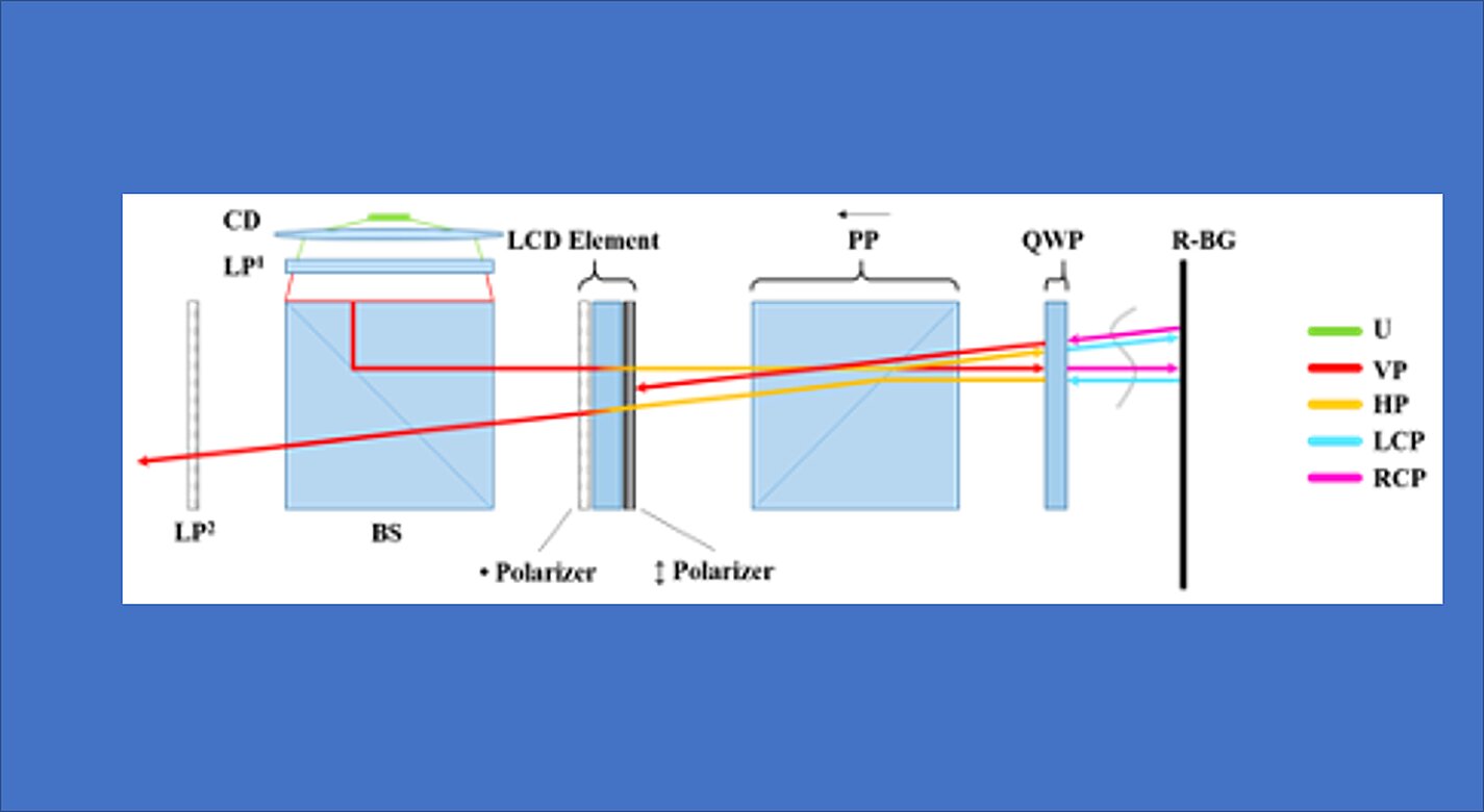
NASAs digital projection focusing schlieren system is attached to a commercial-off-the-shelf camera. For focusing schlieren measurements, it directs light from the light source through a condenser lens and linear polarizer towards a beam-splitter where linear, vertically-polarized component of light is reflected onto the optical axis of the instrument. The light passes through the patterned LCD element, a polarizing prism, and a quarter-wave plate prior to projection from the assembly as left- or right-circularly polarized light. The grid-patterned light (having passed through the LCD element) is directed past the density object onto a retroreflective background (RBG) that serves as the source grid. Upon reflection off the RBG, the polarization state of light is mirrored. It passes the density object a second time and is then reimaged by the system. Upon encountering the polarizing prism the second time, the light is slightly offset. This refracted light passes through the LCD element, now serving as the cutoff grid, for a second time before being imaged by the camera.
The LCD element can be programmed to display a variety of grid patterns to enable sensitivity to different density gradients. the color properties of the LCD can be leveraged in combination with multiple colored light sources to enable simultaneous multi-color, multi-technique data collection.


Benefits
- Easy to use: The single grid design is inherently self-aligned and the sensitivity is easy to adjust which simplifies set-up saving time (i.e., hours to days) and expands potential user base to those outside of experts in optical diagnostics instrumentation.
- Multi-functional: The LCD element is programmable and can be changed on the fly to enable simple changes to density gradient sensitivity and simultaneous collection of multiple image-based measurements.
- Off-Axis imaging capability: The LCD grid can be rotated within the assembly enabling flexibility in the region of interest imag ed which is useful in wind tunnels where windows may be upstream or downstream of the object of interest.
- Compact: The optical assembly is small enough to be mounted like a lens in front of a camera for efficient use of space in cramped experimental environments such as wind tunnels.
- Vibration insensitive: The self-aligning nature of the instrument prevents grid misalignment issues
Applications
- Aerospace: Flow visualization, aerodynamics and fluid dynamics R&D
- Manufacturing: Instrument to visualize gas flow or thermal flow imaging for additive manufacturing or semiconductor manufacturing processes
- Thermal Management: Instrument to visualize or monitor heat transfer from sensitive electronic devices (e.g., to diagnose thermal issues or determine efficacy of thermal management solutions)
- Medical: Instrument for contamination control (e.g., mask efficacy, clean room air flows) and diagnostic imaging of air flows or fluid flows
- Ventilation: Instrument to visualize air flow from ventilation systems
Technology Details
instrumentation
LAR-TOPS-349
LAR-19947-1
Compact, self-aligned focusing schlieren system (June 14, 2021) by inventors Brett F. Bathel and Joshua M. Weisberger in Optics Letters: https://doi.org/10.1364/OL.428011
Development of a Self-Aligned Compact Focusing Schlieren System for NASA Test Facilities (December 29, 2021) presentation at AIAA SCITECH 2022 Forum by inventors Brett F. Bathel and Joshua M. Weisberger: https://arc.aiaa.org/doi/abs/10.2514/6.2022-0560
Similar Results

Assembly for Simplified Hi-Res Flow Visualization
NASAs single grid, self-aligned focusing schlieren optical assembly is attached to a commercial-off-the-shelf camera. It directs light from the light source through a condenser lens and linear polarizer towards a polarizing beam-splitter where the linear, vertically-polarized component of light is reflected onto the optical axis of the instrument. The light passes through a Ronchi ruling grid, a polarizing prism, and a quarter-wave plate prior to projection from the assembly as right-circularly polarized light. The grid-patterned light (having passed through the Ronchi grid) is directed past the density object onto a retroreflective background that serves as the source grid. Upon reflection off the retroreflective background, the polarization state of light is mirrored. It passes the density object a second time and is then reimaged by the system. Upon encountering the polarizing prism the second time, the light is refracted resulting in a slight offset. This refracted light passes through the Ronchi ruling grid, now serving as the cutoff grid, for a second time before being imaged by the camera.
Both small- and large-scale experimental set ups have been evaluated and shown to be capable of fields-of-view of 10 and 300 millimeters respectively. Observed depths of field were found to be comparable to existing systems. Light sources, polarizing prisms, retroreflective materials and lenses can be customized to suit a particular experiment. For example, with a high speed camera and laser light source, the system has collected flow images at a rate of 1MHz.

Retroreflective Temperature- and Pressure-Sensitive Paints
The retroreflective-enhanced system combines PSP/TSP with specially treated glass microspheres to enable simultaneous surface and flow field measurements. The process involves a multi-layer coating system including primer, epoxy base coat, and acrylic polymer/ceramic binder, with microspheres applied while the binder retains adhesive properties. The glass microspheres may be uncoated, half-coated with aluminum, or pre-processed to be coated in another chemical. The system leverages dual optical characteristics: the underlying PSP/TSP responds to pressure and temperature changes through luminescence intensity variations at specific wavelengths, while embedded microspheres provide retroreflective properties enabling focused SAFS, shadowgraph, or BOS visualization techniques. This configuration allows simultaneous capture of on-body surface measurements and off-body flow field disturbances. The invention enables measurements from a single viewing orientation rather than requiring orthogonal optical access points. While specific excitation lighting, wavelength filtering, and camera positioning are still necessary, the system significantly streamlines experimental setup compared to traditional separate approaches.
While initially developed for aerodynamic testing and flow visualization research, this invention supports optical measurement and surface analysis applications. By enabling simultaneous measurements from a single optical access point, the retroreflective-enhanced PSP/TSP offers a streamlined solution for systems where optical access limitations are critical. The system is a TRL 6, having undergone successful validation in wind tunnel testing, and is available for patent licensing.

Projected Background-Oriented Schlieren Imaging
The Projected BOS imaging system developed at the NASA Langley Research Center provides a significant advancement over other BOS flow visualization techniques. Specifically, the present BOS imaging method removes the need for a physically patterned retroreflective background within the flow of interest and is therefore insensitive to the changing conditions due to the flow. For example, in a wind tunnel used for aerodynamics testing, there are vibrations and temperature changes that can affect the entire tunnel and anything inside it. Any patterned background within the wind tunnel will be subject to these changing conditions and those effects must be accounted for in the post-processing of the BOS image. This post-processing is not necessary in the Projected BOS process here.
In the Projected BOS system, a pattern is projected onto a retroreflective background across the flow of interest (Figure 1). The imaged pattern in this configuration can be made physically (a pattern on a transparent slide) or can be digitally produced on an LCD screen. In this projection scheme, a reference image can be taken at the same time as the signal image, facilitating real-time BOS imaging and the pattern to be changed or optimized during the measurements. Thus far, the Projected BOS imaging technology has been proven to work by visualizing the air flow out of a compressed air canister taken with this new system (Figure 2).

Reflection-Reducing Imaging System for Machine Vision Applications
NASAs imaging system is comprised of a small CMOS camera fitted with a C-mount lens affixed to a 3D-printed mount. Light from the high-intensity LED is passed through a lens that both diffuses and collimates the LED output, and this light is coupled onto the cameras optical axis using a 50:50 beam-splitting prism.
Use of the collimating/diffusing lens to condition the LED output provides for an illumination source that is of similar diameter to the cameras imaging lens. This is the feature that reduces or eliminates shadows that would otherwise be projected onto the subject plane as a result of refractive index variations in the imaged volume. By coupling the light from the LED unit onto the cameras optical axis, reflections from windows which are often present in wind tunnel facilities to allow for direct views of a test section can be minimized or eliminated when the camera is placed at a small angle of incidence relative to the windows surface. This effect is demonstrated in the image on the bottom left of the page.
Eight imaging systems were fabricated and used for capturing background oriented schlieren (BOS) measurements of flow from a heat gun in the 11-by-11-foot test section of the NASA Ames Unitary Plan Wind Tunnel (see test setup on right). Two additional camera systems (not pictured) captured photogrammetry measurements.

Robotic Assembly of Photovoltaic Arrays
NASA researchers have developed the PAPA technology to increase the efficiency of the thin-film solar array assembly process, significantly decreasing assembly time and labor costs associated with manufacturing large scale solar arrays. Traditional solar cell assembly is a labor intensive, multi-step, time-consuming process. This manual assembly will not be possible in a space environment. To enable solar array assembly in space, PAPA leverages robotic automation to distill the traditional assembly method into four fully automated steps: applying adhesive to block substrate, placing the solar cells using a vacuum tool attached to a universal robotic arm, printing the interconnects and buses to connect the cells, and applying a protective cover.
The PAPA technology is compatible with a variety of thin-film solar cells, including 3D printed cells (essential for future in-space manufacturing of arrays) and terrestrial manufacturing methods. As solar cell technologies mature, PAPA will be able to incorporate advancements into the paneling process. NASA researchers have begun to employ PAPA solar array fabrication and estimate savings of $300-$400/watt. For extraterrestrial assembly of solar panels the size of a football field or larger, PAPA could result in savings of approximately $500 million; a substantial cost savings driven by standardization and efficiency in the solar array assembly process. By demonstrating increases in assembly efficiency, time and cost savings, and passing multiple environmental exposure tests, the PAPA lab protype has completed the final phases of technology development and is ready for scale-up and commercialization.


