Lunar Surface Manipulation System
robotics automation and control
Lunar Surface Manipulation System (LAR-TOPS-73)
Heavy lifting and precise positioning device
Overview
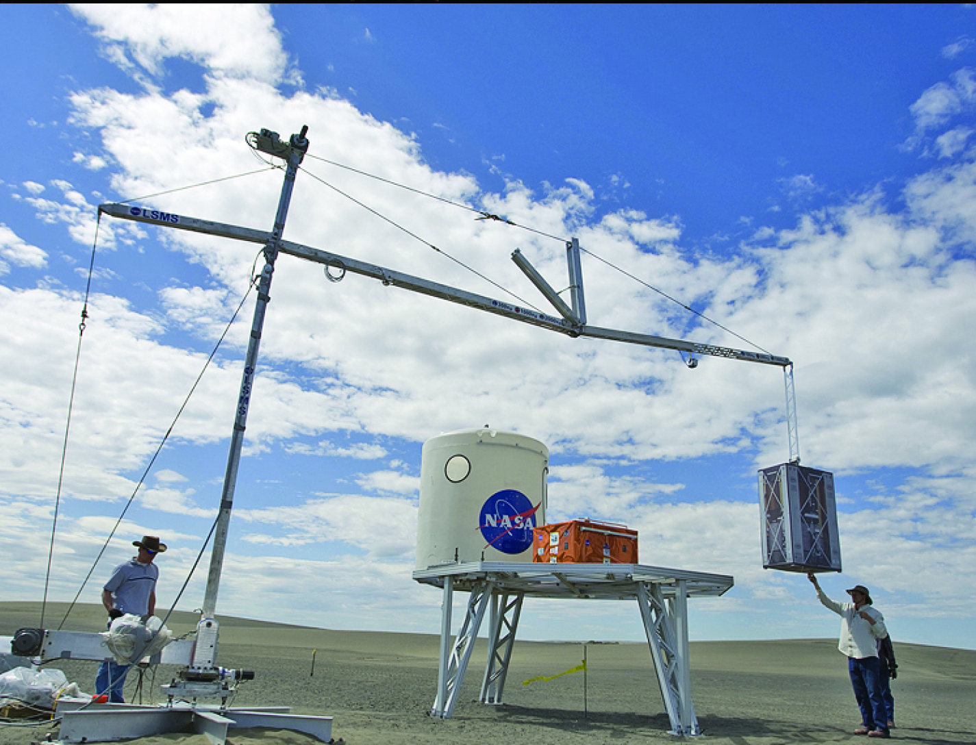
NASA's Langley Research Center offers a novel lifting and precision positioning device with hybrid functional characteristics of both crane-type lifting devices and robotic manipulators. The design of the Lunar Surface Manipulation System (LSMS) allows for fine positioning with complete control over both translation and rotation of the payload. In addition, the design permits several other operations using a wide variety of special purpose tools, such as a bucket, pallet forks, grappling devices, sensor and visualization packages, and dexterous robotic arms that can be quickly added to the tip. NASA is seeking development partners and potential licensees.
The Technology
NASA Langley developed the LSMS because of the need for a versatile system capable of performing multiple functions on the lunar surface, such as unloading components from a lander, transporting components to an operational site and installing them, and supporting service and replacement during component life. Current devices used for in-space operations are designed to work on orbit (zero g) only and thus do not have sufficient strength to operate on planetary surfaces. Traditional cranes are specialized to the task of lifting and are not capable of manipulator-type positioning operations.
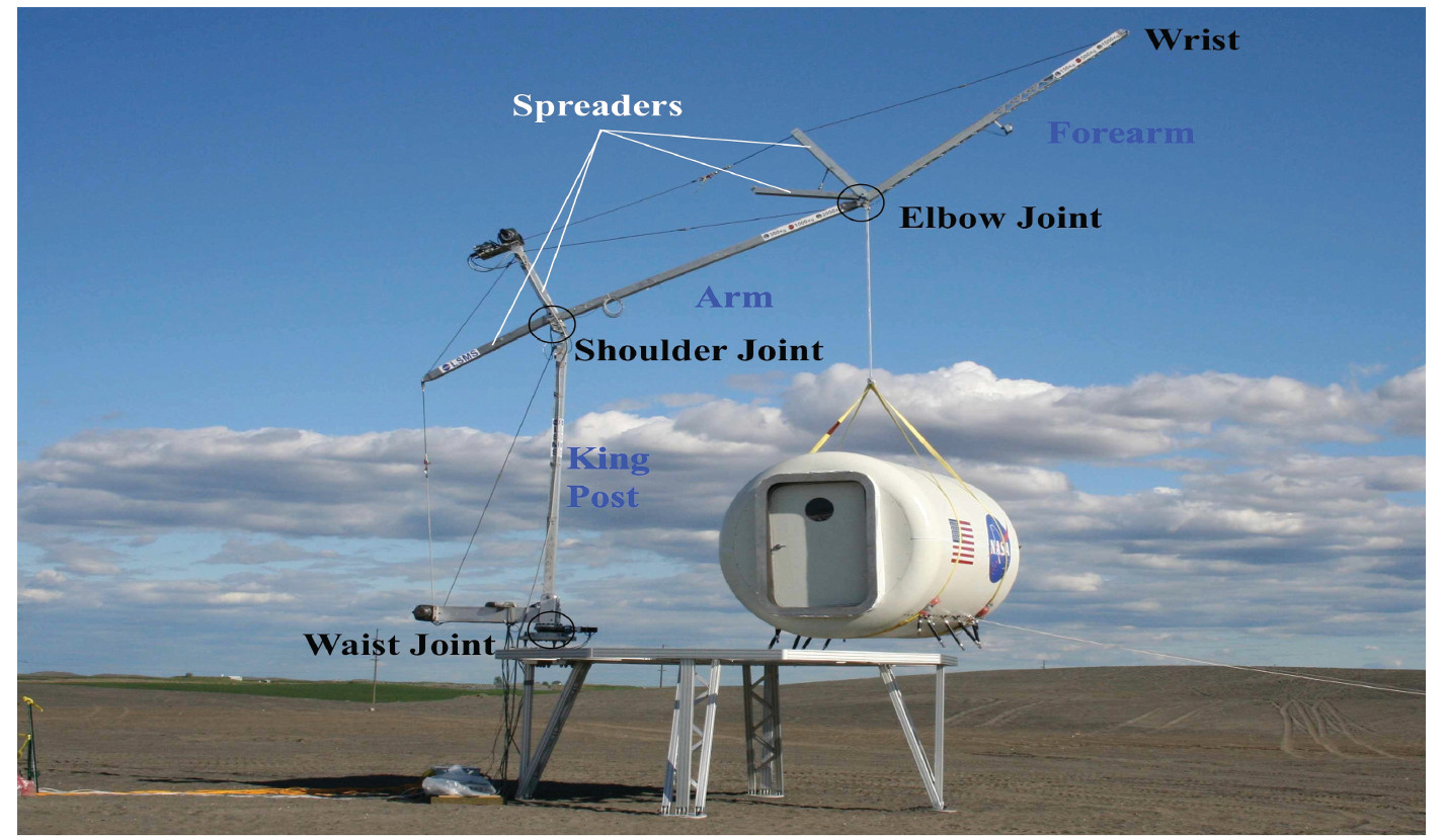
The innovations incorporated into the LSMS allow it to lower payloads to the ground over a significant portion of the workspace without use of a hoist, functioning like a robot manipulator, thus providing a rigid connection and very precise control of the payload. The LSMS uses a truss architecture with pure compression and tension members to achieve a lightweight design. The innovation of using multiple spreaders (like spokes in a wheel) allows the LSMS to maintain its high structural efficiency throughout its full range of motion. Rod portions of the tension members automatically lift off and re-engage the spreaders as the joint articulates, allowing a large range of motion while maintaining mechanical advantage. In addition, the LSMS uses a quick-change device at the tip end that enables automated acquisition of end effectors or special purpose tools to increase its versatility.


Benefits
- Precise positioning for a broad range of heavy lifting operations
- Compact for transport
- Cost-effective
- Scalable and flexible design for customization
- Reliable
- Accommodating of a wide variety of alternate end effectors (or tools)
- Mass efficient
Applications
- Construction - home framing and home roofing
- Hazardous cleanup
- Camera boom operations
- Inspections
- Personnel positioning
- Material handling
- Pipe laying
- Firefighting
Similar Results

Assemblers
Assemblers are a team of modular robots that work together to build things. Each Assembler is a stack of one or more Stewart platforms, or hexapods, made up of two plates connected by six linear actuators for movement, enabling a full six-degree-of-freedom (DOF) pose of the top plate relative to the bottom plate (see figure to the right). An end effector on each Assembler enables gripping, lifting, and welding/joining. The Assemblers system architecture features novel control algorithms and software, sensors, and communicator technology that coordinate operations of Assembler teams. The control system includes an important module for task management that estimates how many robots are needed, the optimal number of hexapods in each Assembler, and the estimated voltage needed. There are also modules for trajectory generation, joint control, sensor fusion, and fault detection. The novel control system directs the Assembler operations for high accuracy and precision, yet there is built-in dynamic resilience to failure. For example, if a single hexapod on an Assembler fails, the system deems it “rigid” in its last pose and redistributes the work to the other Assemblers.
The image below shows a storyboard of operations for how Assemblers might build a solar array. NASA has developed a hardware demo with communications between subsystems, backed up by detailed simulations of the kinematics and actuator dynamics.

Reversible Androgynous Mechanical Fastener
The androgynous fastener is lightweight and facilitates assembly through simple actuation with large driver-positioning tolerance requirements. This fastener provides a high-strength, reversible mechanical connection and may be used in high strength-to-weight ratio structural systems, such as lattice structure systems. The androgynous fastener resists tensile and shear forces upon loading of the lattice structure system thereby ensuring that the struts of the lattice structure system govern the mechanical behavior of the system. The androgynous fastener eliminates building-block orientation requirements and allows assembly in all orthogonal build directions. This androgynous fastener may be captive in building-block structural elements thereby minimizing the logistical complexity of transporting additional fasteners. Integration of a plurality of the androgynous fasteners into a high performance, robotically managed, structural system reduces launch energy requirements, enables higher mission adaptivity and decreases system life-cycle costs. The androgynous fastener is beneficial in any application where robotic end effectors are used to join structural components (or other parts) together. It may be particularly desirable for applications requiring frequent movement of hardware to an assembly site to replace joint connections.

Robotic system for assembly and maintenance of lightweight reconfigurable structures
To enable the goal of autonomous assembly of high performing structures, a robot system must be able to travel across a lattice structure in all dimensions, transport and align a unit cell module to the correct location and fasten the module to the existing structure. In this system, a team of multiple mobile bipedal robots work together to carry, transfer, and place 3D-lattice modules (e.g., cuboctahedron voxels) to form a 3D lattice structure. The team of mobile bipedal robots autonomously provide transportation, placement, unpacking, and assembly of voxel modules into functional structures and systems. As the team of mobile bipedal robots live and locomote on the 3D-lattice structure, they monitor health and performance, enabling repair and reconfiguration when needed. The mobile bipedal robots work together in different roles, for example, one as a cargo transport robot and the other as a crane robot. The cargo transport robot and the crane robot work together to move the voxels from one location to another. Each robot includes at least one electronic control module that receives commands from another robot or a central control system. A central control system implements a plan to control the motion sequences of the robots to maximize efficiency and to optimize the work required to completely assemble a structure. The plan is pre-computed or computed during implementation by the central control system or the robots themselves, according to algorithms that utilize the regularity of the lattice structure to simplify path planning, align robotic motions with minimal feedback, and minimize the number of the degrees of freedom required for the robots to locomote across and throughout the 3D-lattice structure and perform structural assembly.

eVTOL UAS with Lunar Lander Trajectory
This NASA-developed eVTOL UAS is a purpose-built, electric, reusable aircraft with rotor/propeller thrust only, designed to fly trajectories with high similarity to those flown by lunar landers. The vehicle has the unique capability to transition into wing borne flight to simulate the cross-range, horizontal approaches of lunar landers. During transition to wing borne flight, the initial transition favors a traditional airplane configuration with the propellers in the front and smaller surfaces in the rear, allowing the vehicle to reach high speeds. However, after achieving wing borne flight, the vehicle can transition to wing borne flight in the opposite (canard) direction. During this mode of operation, the vehicle is controllable, and the propellers can be powered or unpowered.
This NASA invention also has the capability to decelerate rapidly during the descent phase (also to simulate lunar lander trajectories). Such rapid deceleration will be required to reduce vehicle velocity in order to turn propellers back on without stalling the blades or catching the propeller vortex. The UAS also has the option of using variable pitch blades which can contribute to the overall controllability of the aircraft and reduce the likelihood of stalling the blades during the deceleration phase.
In addition to testing EDL sensors and precision landing payloads, NASA’s innovative eVTOL UAS could be used in applications where fast, precise, and stealthy delivery of payloads to specific ground locations is required, including military applications. This concept of operations could entail deploying the UAS from a larger aircraft.

Robotic gripper for satellite capture and servicing
The Gripper is located at the end of a robotic system consisting of a robotic arm equipped with a Tool Drive or End Effector comprising the input actuator to the Gripper as well as the structural, power and data link between the Gripper and the robotic arm. In a notional concept of operations, a Servicer would approach the Client in an autonomous rendezvous and capture (AR&C) maneuver. When the Servicers sensor suite confirms that the distance, orientation, and relative translational and angular rates with respect to the Client are within an acceptable range, the Servicer enables the grasping sequence, where the robotic arm, equipped with Gripper, extend forward to the Client. When the Gripper/ Servicer sensors indicate that the Client marman ring is sufficiently within the capture range of the Gripper, a trigger signal is sent to the robot control system that commands the End Effector to drive the mechanism of the Gripper and affect closure around the marman ring. The Gripper consists of a pair of jaws which are driven by an internal transmission. The transmission receives input torque from the End Effector and converts the torque to appropriate motion of the jaws.


