Anti-Phase Noise Suppression Rotor Technologies
Aerospace
Anti-Phase Noise Suppression Rotor Technologies (TOP2-297)
Acoustic Optimization for Anti-Phase Asymmetric Rotor
Overview
All rotorcraft experience rotor noise and vibration that present operational challenges due to the unsteady forces that result from blade vortex shedding. Rotor noise is often a nuisance, and excessive rotor vibration can be hazardous. Several methods exist to deal with the noise and vibration from rotor blades, though many designs either aim to reduce vibration and do not address noise, or vice versa. NASA Ames Research Center has developed a novel patent-pending design and method for reducing rotor blade vibration and acoustic signatures in rotor systems using anti-phase blade vortex suppression design concepts. The design objective is to maximize reduction of noise perceived by the community while maintaining the aerodynamic thrust. These designs could be applicable in any system that uses rotor blades.
The Technology
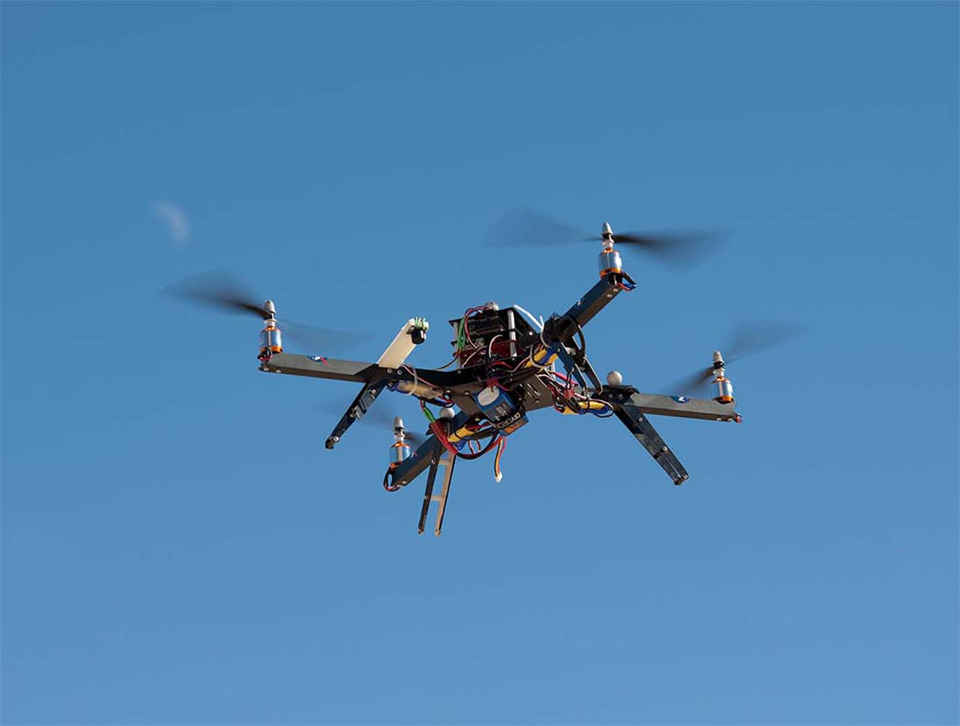
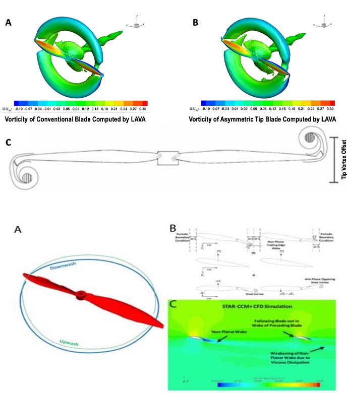
Rotor noise and vibration are two sources of operational challenges for all aircraft operating with open rotors such as helicopters, unmanned aerial vehicles (UAVs), urban air mobility personal air vehicles, drones, and aircraft operating with ducted fans such as passenger aircraft. One disadvantage of convention rotor design is the noise due to noise-induced shed vortices generated by rotor blades. The unique problem with rotor noise and vibration is the periodic blade passage that causes a harmonic reinforcement and causes the rotor blades to vibrate and generate noise sources. This technology from NASA Ames seeks to optimize the implementation of anti-phase trailing edge designs and asymmetric blade tip treatments for rotor noise suppression and integrated aircraft noise solutions by incorporating the anti-phase rotor design concepts into an aircraft flight control system to reduce noise footprint. There are several embodiments of the invention, which include the following: (1) an anti-phase trailing edge design whereby the trailing edge pattern of the leading rotor blade is offset by a phase shift from the trailing edge pattern of the following blade; (2) an anti-phase rotor design implementing asymmetric blade tips with inverted airfoil; and (3) other anti-phase enabled concepts such as unequal blade length, ducted rotors with non-radial unequally spaced struts, and multi-axis tilt rotor design incorporating the anti-phase rotor design.
Benefits
- Reduces noise from rotor blades: reduces the acoustic signatures made by rotorcraft during operation, providing noise reduction both for passengers inside the vehicle and community noise reduction for people on the ground
- Reduces vibrations in systems with rotor blades: allows for more stable aircraft operation and improved performance of rotor systems
- Increases thrust: creates more thrust than the standard baseline rotor blade design at the same RPM, thereby allowing rotors to operate at lower RPMs for noise reduction
- The designs could be applicable in any system that uses rotor blades
Applications
- Rotorcraft like helicopters
- Drones/Unmanned Aerial Vehicles (UAVs)
- Military/commercial/passenger aircraft
- Urban Air Mobility Vehicles (UAMV)
- Gas turbine engines; Wind turbines
- Power plants
- Industrial systems that uses rotor blades
Technology Details
Aerospace
TOP2-297
ARC-18169-1
https://arc.aiaa.org/doi/abs/10.2514/6.2020-1496
https://arc.aiaa.org/doi/abs/10.2514/6.2019-1070
https://arc.aiaa.org/doi/abs/10.2514/6.2019-1070
Similar Results

Integral Tuned Mass Absorber for Turbine Blades
Additive manufacturing methods (e.g. Laser Metal Sintering) are used to integrally fabricate a tuned-mass vibration absorber inside a turbine blade. The design approach uses an internal column manufactured as part of the blade that is optimized such that the dynamics of the blade damper system are rearranged and reduced according to the well-known science of tuned mass-absorption (TMA). The TMA concept has been implemented successfully in applications ranging from skyscrapers to liquid oxygen tanks for space vehicles. Indeed, this theory has been conceptually applied to bladed-disk vibration, but a practical design has not previously been reported.
The NASA innovation addresses another important challenge for turbine blade vibration damper designs. All existing blade damper solutions are essentially incapable of being reliably predicted, so an expensive post-design test program must be performed to validate the expected response. Even then, the actual magnitude of the response reduction under actual hot fire conditions may never be known. The dynamic response of this tuned-mass-absorber design is both substantial and can be analytically predicted with high confidence, and thus the response can be incorporated fully into the up-front design process.

Device for Providing Real-Time Rotorcraft Noise Abatement Information
The magnitude and direction of rotor noise radiation is determined by the aerodynamic operating state of the rotor commonly referred to as the "Blade-Vortex Interaction" which occurs when the wake vortex trailing from a preceding rotor blade interacts with the front edge of the following rotor blade. The wake vortex causes a rapid change in the blade loading, which results in the generation of high amplitude, impulsive, and highly directional noise. The occurrence, magnitude, and directionality of Blade-Vortex Interaction noise is very sensitive to the rotor operating state because it is dependent on the relative positions of the rotor and its vortex wake. By providing the rotorcraft pilot with information about annoying noise levels currently being emitted by the rotorcraft and its effects on the ground, corrective action can be taken to change the operating state of the vehicle to minimize or avoid annoyance due to such rotor noise sources.
During operation, the pilot would activate the device before or during operation of the rotorcraft. The device displays the noise abatement information through a display unit, informing the pilot about the current acoustic state of the vehicle and providing guidance on how to change the vehicle performance and acoustic state to avoid objectionable blade-vortex Interaction noise. Annoyance footprint information can then be used by the pilot to change the flight path of the vehicle such that the annoyance footprint will not extend into noise sensitive areas.

A New Twist Makes Rotating Machinery More Efficient and Quieter
Derived from a design approach for a new wing known as PRANDTL-D, this technology achieves similar improvements for propellers and other rotating machinery.
How It Works
To achieve the innovation's alternate spanload, Armstrong designers applied a non-linear twist to the propeller blade. The twist moves the load inward and dissipates the tip vortex over a wider area, minimizing its effect on drag. It also results in a decrease in load at the tip and reduced torque at the tip. These changes combine to achieve a dramatic reduction in power consumption without compromising the blade's other parameters. Specifically, the blade's diameter and rpm remain unchanged.
What Makes It Better
Unlike the conventional minimum induced loss (elliptical) spanload, which consumes large amounts of power at the tip of the blade, the new design unloads the tip and reduces torque, achieving significant improvements in efficiency. First-order analysis shows a more than 15 percent improvement in power consumption while producing the same thrust. The design also produces significantly less noise than conventional blade designs.

Periodic Wave Disc Brake Rotor
The NASA Periodic Wave Disc Brake Rotor is novel yet elegantly simple and cost-effective design to maximize weight reduction and heat dissipations. This is accomplished through NASA's proprietary concept of combining the forced convection, radiation, and conduction of air flow over the brake rotor's surface. Depending upon the application, a dramatic reduction of the rotor material itself can be selected from either steel, oxygen-diffused titanium, or an aluminum forging alloy.
A two-piece floating rotor assembly is designed to further reduce the weight of the rotor's mounting hub and its rotational moment of inertia, while simultaneously minimizing the rotor's thermal expansion, stress, warping, or distortion experience during extreme frictional heating generated from repeated hard braking actions under high speed racing conditions.

Reverse Vortex Ring (RVR)
Vibration problems, which occur more frequently in high power to weight machines, often lead to costly down time, subsequent redesign, and, in some instances, catastrophic failure. A disproportionate number of vibration problems in rotating machinery can be attributed to highly pre-swirled fluid entering tight clearance locations such as seals and fluid bearings. The relationship between high fluid pre-swirl and undesirable vibration issues is clear. Machines with high levels of fluid pre-swirl are more susceptible to instabilities and vibration problems.
A top priority in rotor dynamic design, therefore, is to develop devices to minimize the level of fluid pre-swirl entering tight clearance locations. The RVR was designed to condition the flow prior to entering the seal (or axial flow fluid-film bearing) so that the flow through the annular clearance is at a minimum purely axial. While conventional swirl brakes have only been shown to reduce pre-swirl by up to 30%, the RVR can actually reverse the direction of the swirl, so that circumferential fluid velocity flows in a direction counter to shaft rotation. Thus, a classic detriment to rotating machinery has now become an asset to ameliorate vibration issues through the RVR.
The RVR is axially efficient, typically increasing the axial length of a smooth annular seal on the order of 10-12%.
The RVR has been extensively tested and is now in use at NASA.



