Freeze-Resistant Hydration System
environment
Freeze-Resistant Hydration System (MSC-TOPS-21)
Portable drinking bladder designed for rugged, cold, and high-altitude conditions
Overview
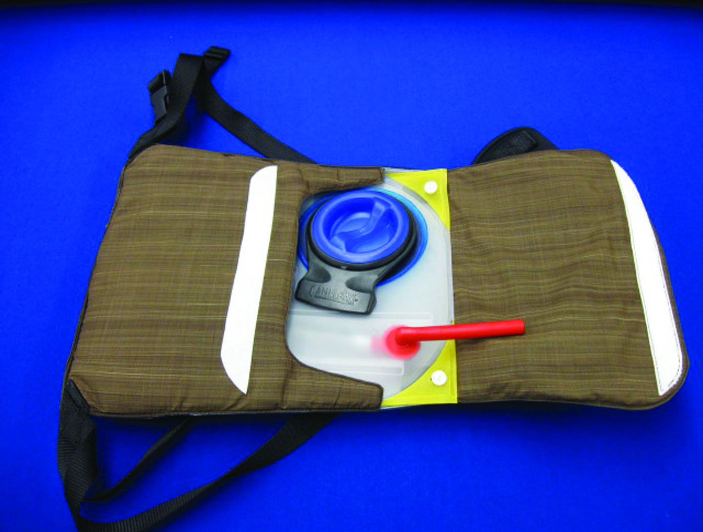
NASA's Johnson Space Center is offering an innovative freeze-resistant hydration system for licensing. The technology substantially improves on existing hydration systems because it prevents water from freezing in the tubing, container, and mouthpiece, even in the harshest conditions on Earth. This technology is designed to work to minus 40 degrees Celsius and 15-mile-per-hour winds over a 12-hour summit day, and likely well beyond. Field testing was performed at Mt. Everest in May 2009. The device was originally conceived and designed by an astronaut-mountaineer who recognized the great risk of dehydration in high mountains and the lack of sufficient technology to meet this important need.
This NASA Technology is available for your company to license and develop into a commercial product. NASA does not manufacture products for commercial sale.
The Technology
Even when a water conformal fluid reservoir and drink straw are zipped into a down suit, water freezes under extreme conditions. This poses a health hazard, particularly to high-altitude climbers who mouth-breathe, as mouth-breathing causes substantial fluid loss (in exhaled breaths). Climbers of 8,000-meter peaks get only 1 liter or less of fluid on summit days because their drink bottles freeze so quickly.
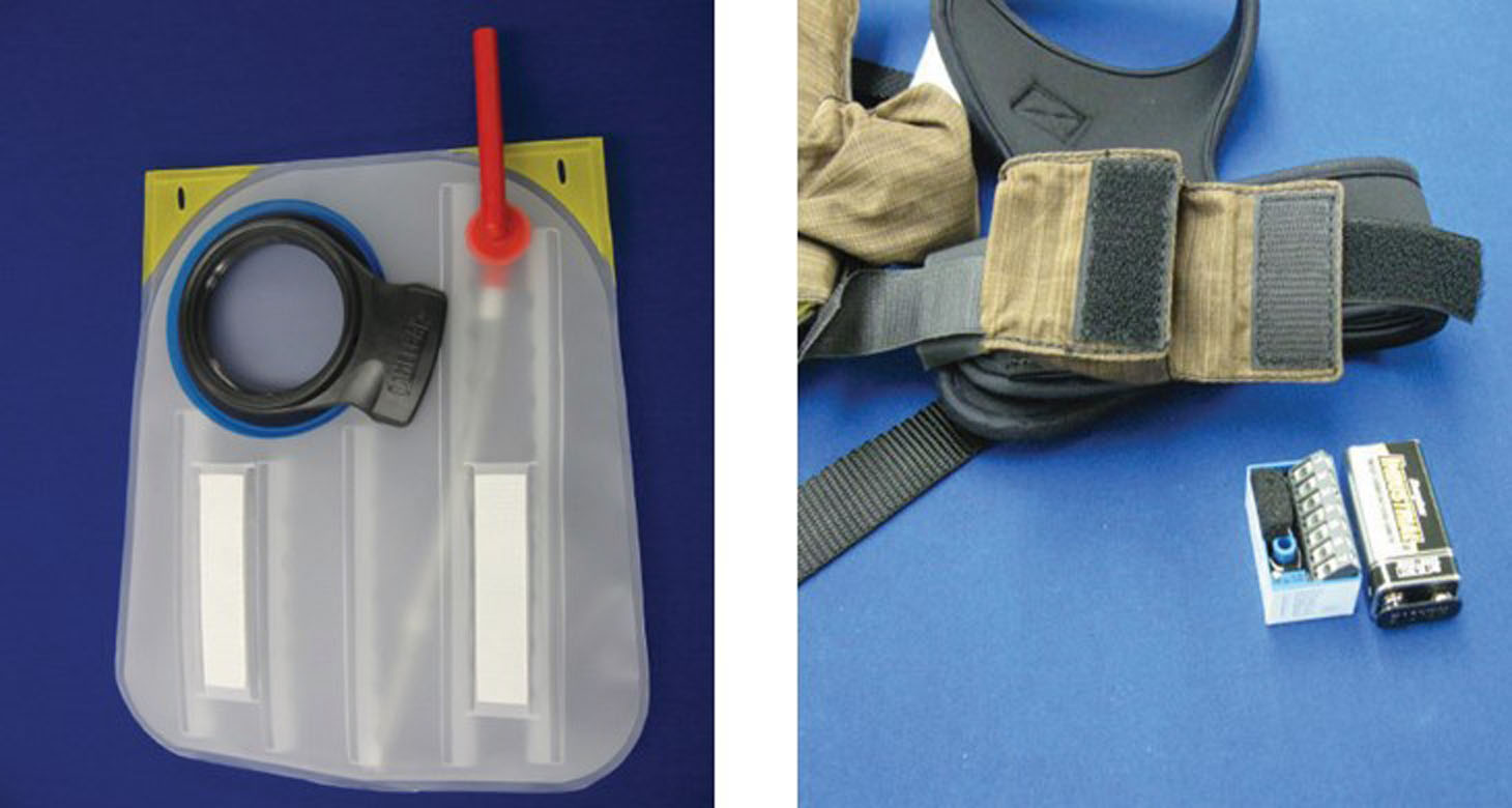
The High Altitude Hydration System keeps water from freezing in three different ways. First, the system has passive thermal control that uses aerogel insulation on the outside of the conformal fluid reservoir and around the drinking straw to protect the contents from the cold. The container is placed within an inner layer of clothing, and the insulated straw is pulled out from underneath the suit for sips. Second, the system has a braided copper wire placed around the exterior of the drinking straw and another heat-collecting surface about the container wall to transfer body-generated heat to the fluid reservoir and straw during use. Third, the system uses a microcontroller and tape heater powered by a battery to keep the straw warm and free of ice crystals.


Benefits
- Improved safety: Provides 2-3 liters of liquid beverage for a full summit day
- Lightweight: The system is insulated with lightweight aerogel material
- Flexibility: Uses passive and active subsystems to keep water from freezing
Applications
- Mountain climbers
- Cross-country skiers
- Snowmobilers
- Law enforcement and rescue personnel
- Defense environments, including underwater and deep sea use
- Downhill skiers
- Winter campers
Similar Results

Cryostat-100
Cryostat-100 combines the best features of previous cryostats developed by NASA, while offering new features and conveniences. This unit can readily handle the full range of cryogenic-vacuum conditions over several orders of magnitude of heat flux. Guide rings, handling tools, and other design items make insulation change-out and test measurement verification highly reliable and efficient to operate. The new apparatus requires less ancillary equipment (it is not connected to storage tank, phase separator, subcooler, etc.) to operate properly. It is top-loading, which makes disassembly, change-out, and instrumentation hook-up much faster. The thermal stability is improved because of internal vapor plates, a single-tube system of filling and venting, bellows feed-throughs, Kevlar thread suspensions, and heavy-wall stainless-steel construction.
The cold mass of Cryostat-100 is 1m long, with a diameter of 168 mm. The test articles can therefore be of a corresponding length and diameter, with a nominal thickness of 25.4 mm. Shorter lengths are acceptable, and thicknesses may be from 0 mm to 50 mm. Tests are conducted from ambient pressure (760 torr) to high vacuum (below 110-4 torr) and at any vacuum pressure increment between these two extremes. The residual gas (and purge gas) is typically nitrogen but can be any purge gas, such as helium, argon, or carbon dioxide.
Typically, eight cold vacuum pressures are performed for each test series. The warm boundary temperature is approximately 293 K, and the cold boundary temperature is approximately 78 K. The delta temperature for the cryogenic testing is therefore approximately 215 K. A unique lift mechanism provides for change-out of the insulation test specimens. It also provides for maintenance and other operations in the most effective and time-efficient ways. The lift mechanism is also a key to the modularity of the overall system.

Contaminated Water Treatment
This invention is a system and associated method that is a two step process. It provides a contaminant treatment pouch, referred to as a urine cell or contaminant cell that converts urine or another liquid containing contaminants into a fortified drink, engineered to meet human hydration, electrolyte and caloric requirements. It uses a variant of forward osmosis (FO) to draw water from a urine container into the concentrated fortified drink as part of a recycling stage. An activated carbon pretreatment removes most organic molecules. Salinity of the initial liquid mix (urine plus other) is synergistically used to enhance the precipitation of organic molecules so that activated carbon can remove most of the organics. A functional osmotic bag is then used to remove inorganic contaminants. If a contaminant is processed for which the saline content is different than optimal for precipitating organic molecules, the saline content of the liquid should be adjusted toward the optimal value for that contaminant.

Macroflash (Cup Cryostat)
Advances in new polymers and composites along with growing industrial needs in below-ambient temperature applications have brought about the Macroflash development. Accurate thermal performance information, including effective thermal conductivity data, are needed under relevant end-use conditions. The Macroflash is a practical tool for basic testing of common materials or research evaluation of advanced materials/systems.
The Macroflash can test solids, foams, or powders that are homogeneous or layered in composition. Test specimens are typically 75mm in diameter and 6mm in thickness. The cold side is maintained by liquid nitrogen at 77 K while a heater disk maintains a steady warm-side temperature from ambient up to 373 K. The steady boiloff of the liquid nitrogen provides a direct measure of the heat energy transferred through the thickness of the test specimen. Nitrogen or other gas is supplied to the instrument to establish a stable, moisture-free, ambient pressure environment. Different compression loading levels can also be conveniently applied to the test specimen as needed for accurate, field-representative thermal performance data. The Macroflash is calibrated from approximately 10 mW/m-K to 800 mW/m-K using well-characterized materials.

Cryostat-500
The Cryostat-500 provides laboratory measurement of the steady-state thermal transmission properties of thermal insulation systems under conditions below ambient temperature. Liquid nitrogen is used as a direct measure of the energy going through the test specimen. Thermal insulation systems may be composed of one or more materials that may be homogeneous or non-homogeneous at boundary conditions from 77 K to 373 K and in environments from high vacuum (10E-7 torr) to ambient pressure (10E+3 torr).
The Cryostat-500 provides a much wider range of thermal performance and covers the full range of environmental conditions for applications below ambient temperature. The instrument has been proven through extensive testing of foams, composite panels, multilayer insulation (MLI) systems, aerogel blankets, fiberglass, and many other types of materials. Both the quality and quantity of the thermal performance data for insulation materials and systems have increased even as the process and method has become more time efficient and cost effective. Further guidelines on the test method and equipment for the Cryostat-500 are given in ASTM C1774, Annex A3.

Air Revitalization for Vacuum Environments
The NASA life support system uses a regenerable vacuum swing adsorption process, known as Sorbent-Based Air Revitalization (SBAR), to separate water and carbon dioxide for disposal. The SBAR system is an adsorbent-based swing bed system that has been optimized to provide both humidity and carbon dioxide control for a spacecraft cabin atmosphere.
The system comprises composite silica gel and zeolite-packed beds for adsorption and a bypass system for flow control. Under normal operating conditions, the disposal system would require a high-quality vacuum environment to operate. Improvements to the SBAR system include an enhanced inherent capacitance that extends the operation time within a non-vacuum environment for up to 4.5 hours. Flight time can be further expanded with multiple SBAR systems to allow for system regeneration. By scheduling periodic thermal regenerations—nominally during sleep periods—the SBAR technology may be suitable for missions of unlimited duration.


