Search
Instrumentation
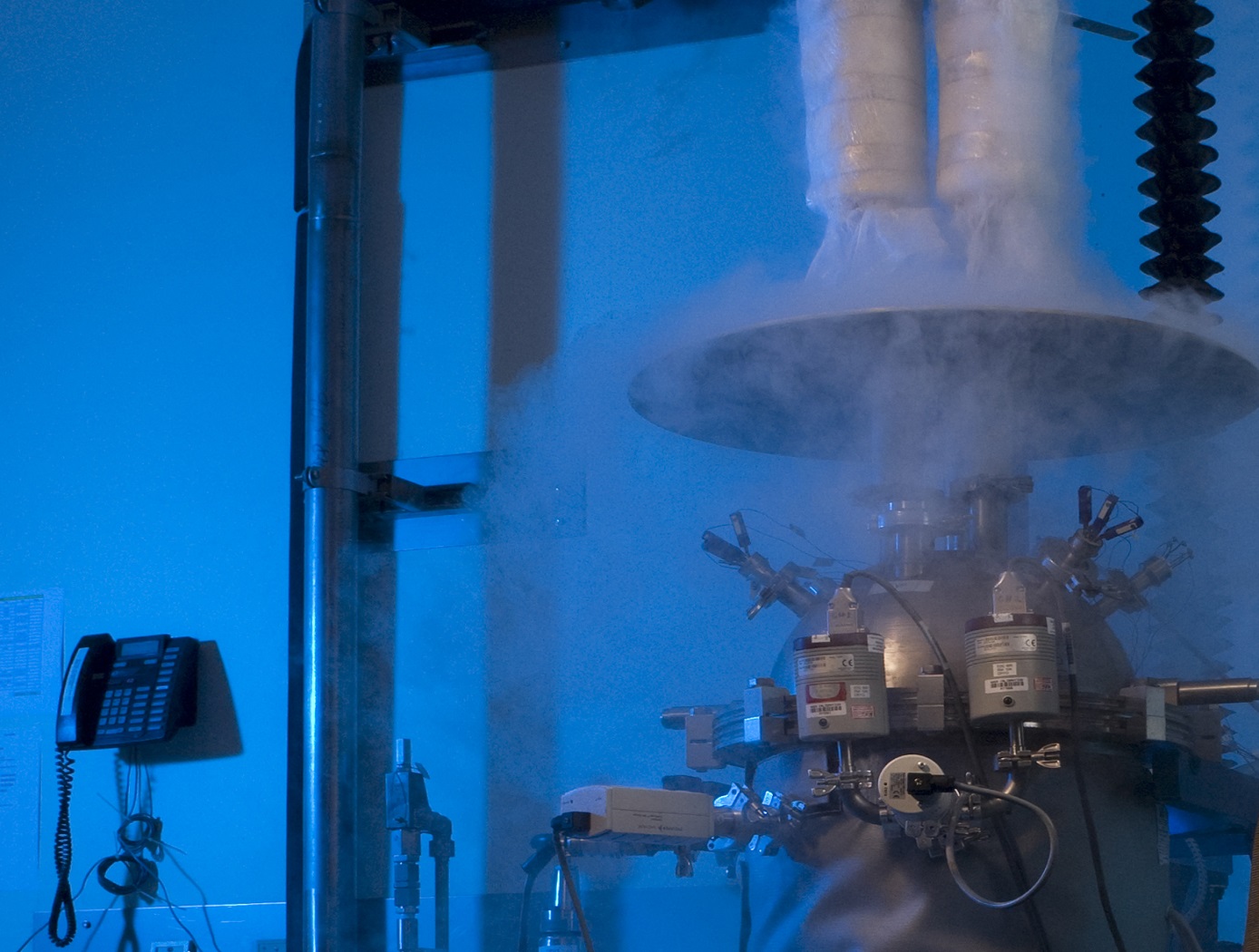
Cryostat-100
Cryostat-100 combines the best features of previous cryostats developed by NASA, while offering new features and conveniences. This unit can readily handle the full range of cryogenic-vacuum conditions over several orders of magnitude of heat flux. Guide rings, handling tools, and other design items make insulation change-out and test measurement verification highly reliable and efficient to operate. The new apparatus requires less ancillary equipment (it is not connected to storage tank, phase separator, subcooler, etc.) to operate properly. It is top-loading, which makes disassembly, change-out, and instrumentation hook-up much faster. The thermal stability is improved because of internal vapor plates, a single-tube system of filling and venting, bellows feed-throughs, Kevlar thread suspensions, and heavy-wall stainless-steel construction.
The cold mass of Cryostat-100 is 1m long, with a diameter of 168 mm. The test articles can therefore be of a corresponding length and diameter, with a nominal thickness of 25.4 mm. Shorter lengths are acceptable, and thicknesses may be from 0 mm to 50 mm. Tests are conducted from ambient pressure (760 torr) to high vacuum (below 110-4 torr) and at any vacuum pressure increment between these two extremes. The residual gas (and purge gas) is typically nitrogen but can be any purge gas, such as helium, argon, or carbon dioxide.
Typically, eight cold vacuum pressures are performed for each test series. The warm boundary temperature is approximately 293 K, and the cold boundary temperature is approximately 78 K. The delta temperature for the cryogenic testing is therefore approximately 215 K. A unique lift mechanism provides for change-out of the insulation test specimens. It also provides for maintenance and other operations in the most effective and time-efficient ways. The lift mechanism is also a key to the modularity of the overall system.
Materials and Coatings
Aerofoam
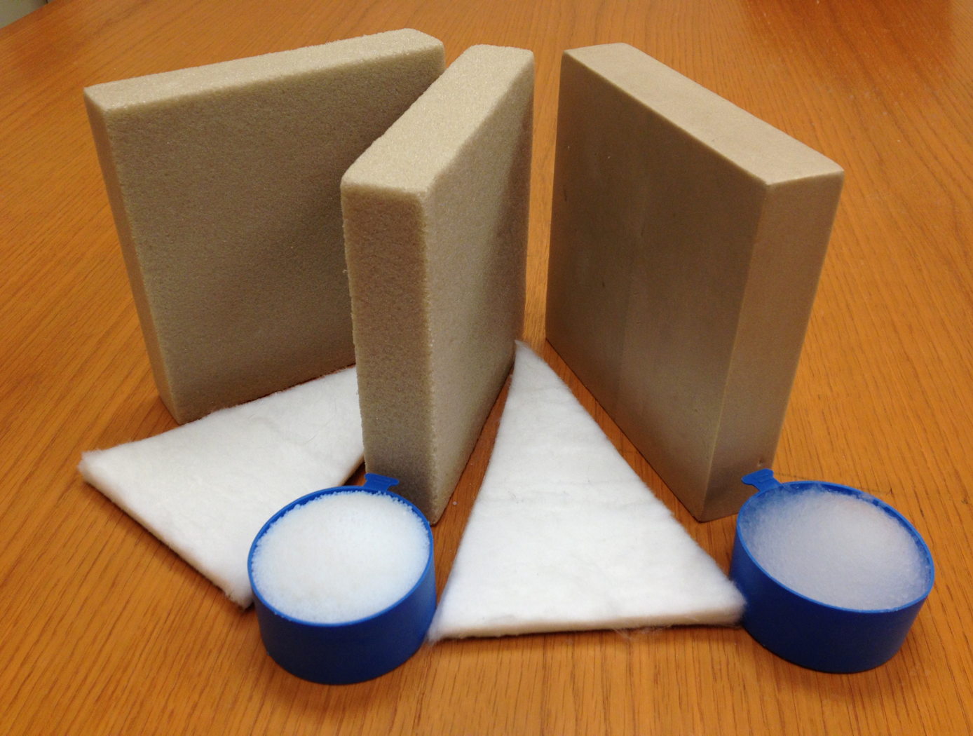
The Aerofoam composites have superior thermal and acoustic insulation properties when compared to conventional polyimide foams. In addition, they provide greater structural integrity than the fragile aerogel materials can provide independently. In general, polymer foams can provide excellent thermal insulation, and polyimide foams have the additional advantage of excellent high-temperature behavior and flame resistance compared to other polymer systems (they do not burn or release noxious chemicals). Incorporating aerogel material into the polyimide foam as described by this technology creates a composite that has been demonstrated to provide additional performance gains, including 25% lower thermal conductivity with no compromise of the structural integrity and high-temperature behavior of the base polyimide foam. The structural properties of Aerofoam are variable based on its
formulation, and it can be used in numerous rigid and flexible foams of varying densities.
Aerofoam has a number of potential commercial applications, including construction, consumer appliances, transportation, electronics, healthcare, and industrial equipment. In addition, these high-performance materials may prove useful in applications that require insulation that can withstand harsh environments, including process piping, tanks for transporting and storing hot or cold fluids, ship and boat building, and aerospace applications.
materials and coatings
Polyamide Aerogels
Polyamides are polymers that are similar to polyimides (another polymer that has been developed for use in aerogels). However, because the amide link is a single chain while the imide link is a ring structure, polyamide aerogels can be made less stiff than polyimides, even though a similar fabrication process is used. The precursor materials can be made from any combination of diamine and diacid chloride. Furthermore, NASA Glenn researchers have found methods for using combinations of diamines and disecondary amines to produce polyamide aerogels with tunable glass transition temperatures, for greater control of features such as flexibility or water-resistance.
In the first step of the fabrication process, an oligomeric solution is produced that is stable and can be prepared and stored indefinitely as stock solutions prior to cross-linking. This unique feature allows for the preparation and transport of tailor-made polyamide solutions, which can later be turned into gels via the addition of a small amount of cross-linker. When the cross-linking agent is added, the solution can be cast in a variety of forms such as thin films and monoliths. To remove the solvent, one or more solvent exchanges can be performed, and then the gel is subjected to supercritical drying to form a polyamide aerogel. NASA Glenn's polyamide aerogels can be fully integrated with the fabrication techniques and products of polyimide aerogel fabrication, so hybrid materials which have the properties of both classes are easily prepared. As the first aerogels to be composed of cross-linked polyamides, these materials combine flexibility and transparency in a way that sets them apart from all other polymeric aerogels.
environment
Freeze-Resistant Hydration System
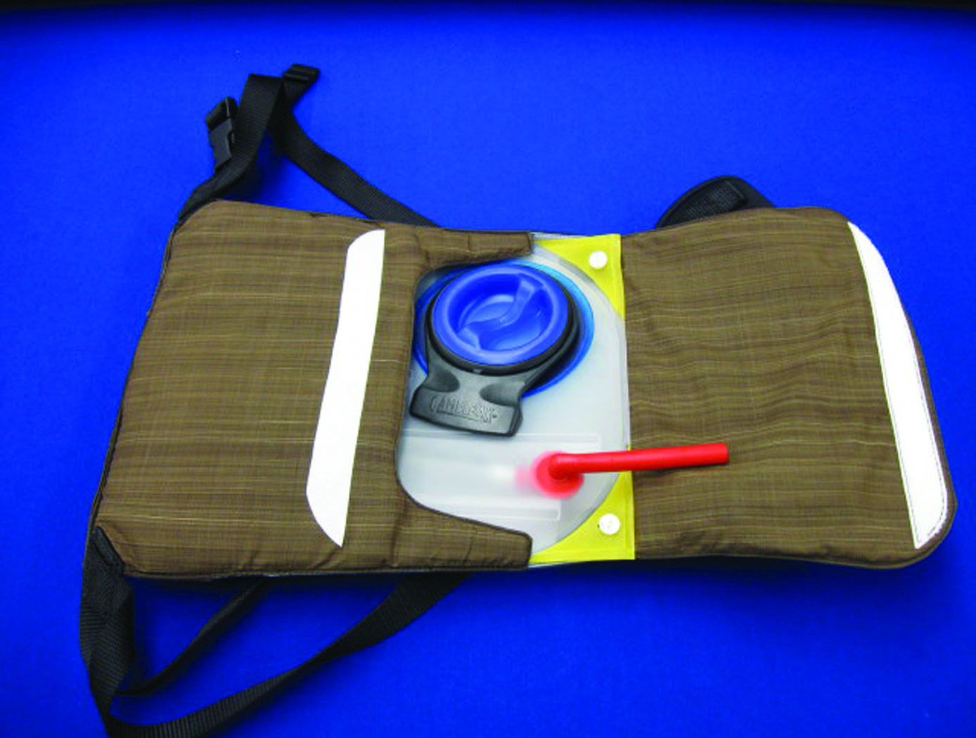
Even when a water conformal fluid reservoir and drink straw are zipped into a down suit, water freezes under extreme conditions. This poses a health hazard, particularly to high-altitude climbers who mouth-breathe, as mouth-breathing causes substantial fluid loss (in exhaled breaths). Climbers of 8,000-meter peaks get only 1 liter or less of fluid on summit days because their drink bottles freeze so quickly.
The High Altitude Hydration System keeps water from freezing in three different ways. First, the system has passive thermal control that uses aerogel insulation on the outside of the conformal fluid reservoir and around the drinking straw to protect the contents from the cold. The container is placed within an inner layer of clothing, and the insulated straw is pulled out from underneath the suit for sips. Second, the system has a braided copper wire placed around the exterior of the drinking straw and another heat-collecting surface about the container wall to transfer body-generated heat to the fluid reservoir and straw during use. Third, the system uses a microcontroller and tape heater powered by a battery to keep the straw warm and free of ice crystals.
Electrical and Electronics
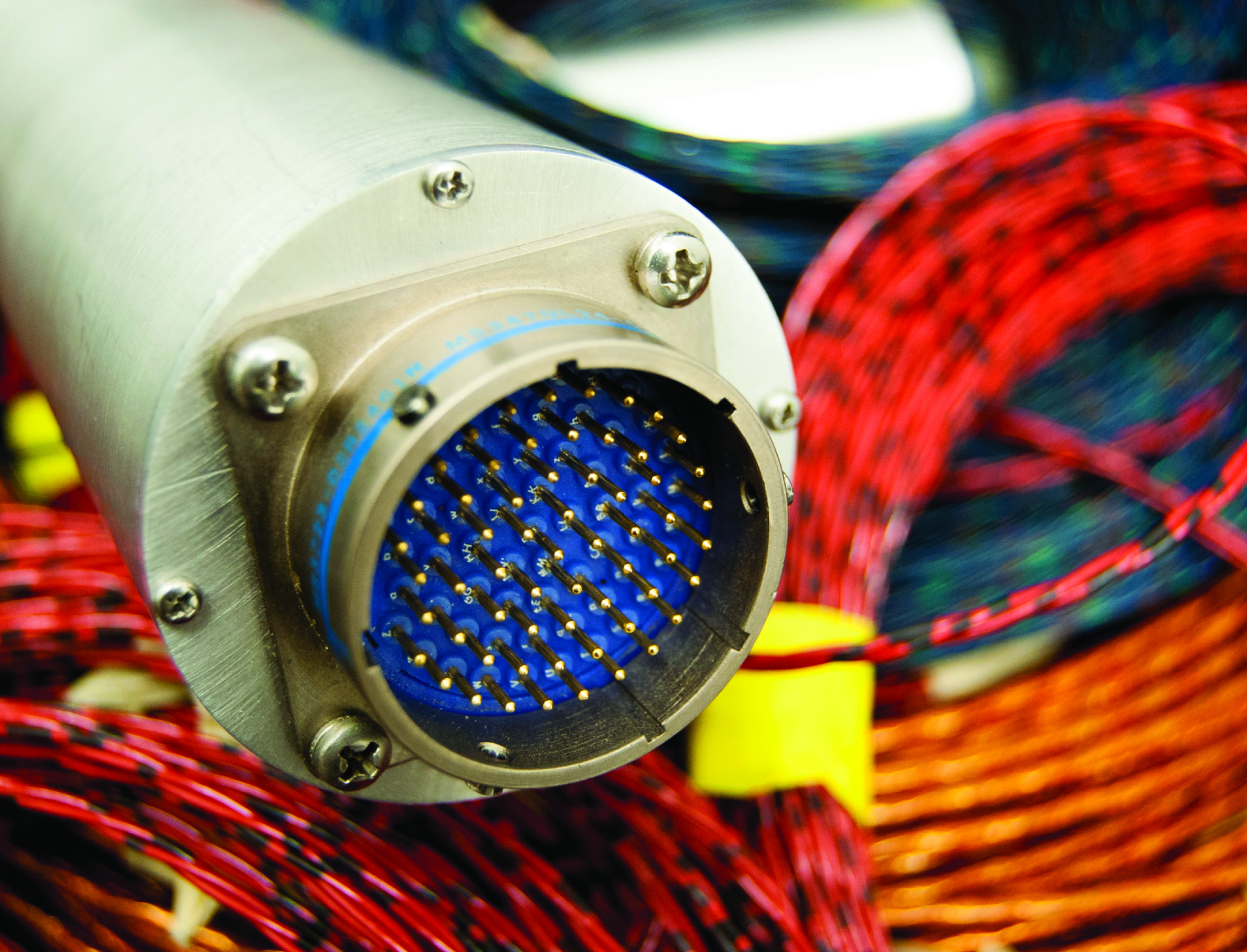
In Situ Wire Damage Detection and Rerouting System
The tester was designed to monitor electrical faults in either online or offline modes of operation. In the online mode, wires are monitored without disturbing their normal operation. A cable can be monitored several times per second in the offline mode, and once per second in the online mode. The online cable fault locator not only detects the occurrence of a fault, but also determines the type of fault (short/open/intermittent) and the location of the fault. This enables the detection of intermittent faults that can be repaired before they become serious problems. Since intermittent faults occur mainly during operations, a built-in memory device stores all relevant fault data. This data can be displayed in real time or retrieved later so maintenance and repairs can be completed without spending countless hours attempting to pinpoint the source of the problem.
Hardware and algorithms have also been developed to safely, efficiently, and autonomously transfer electrical power and data connectivity from an identified damaged/defective wire in a cable to an alternate wire path. This portion of the system consists of master and slave units that provide the diagnostic and rerouting capabilities. A test pulse generated by the master unit is sent down an active wire being monitored by the slave unit. When the slave unit detects the test pulse, it routes the pulse back to the master unit through a communication wire. When the master unit determines that a test pulse is not being returned, it designates that wire as faulty and reroutes the circuit to a spare wire.
Sensors
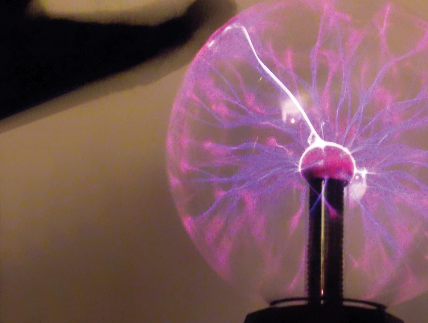
Electric Field Imaging System
The EFI imaging platform consists of a sensor array, processing equipment, and an output device. By registering voltage differences at multiple points within the sensor array, the EFI system can calculate the electrical potential at points removed from the sensor. Using techniques similar to computed tomography, the electrical potential data can be assembled into a three-dimension map of the magnitude and direction of electric fields. Since objects interact with electric fields differently based on their shape and dielectric properties, this electric field data can then be used to understand shape,
internal structure, and dielectric properties (e.g., impedance, resistance) of objects in three dimensions.
The EFI sensor can be used on its own to see electric fields or image electric fieldemitting objects near the sensor (e.g., to evaluate leakage from poorly shielded wires or casings). For evaluation of objects that do not produce an electric field, NASA has developed generator that emits a low-current, human-safe electrostatic field for snapshot evaluation of objects. Additionally, an alternative EFI system optimized to evaluate electric fields at significant distances (greater than 1 mile) is being developed for weather-related applications.
materials and coatings
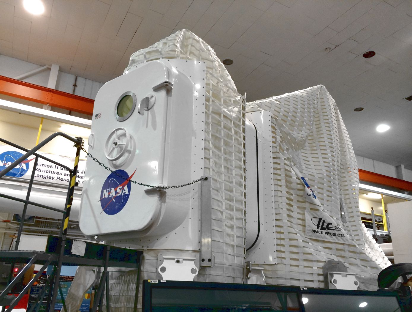
Layered Composite Insulation for Extreme Conditions (LCX)
The approach in developing the LCX system was to provide a combination of advantages in thermal performance, structural capability, and operations. The system is particularly suited for the complex piping, tanks, and apparatus subjected to the ambient environment common in the aerospace industry. The low-cost approach also lends the same technology to industrial applications such as building construction and chilled-water piping. The system can increase reliability and reduce life cycle costs by mitigating moisture intrusion and preventing the resulting corrosion that plagues subambient-temperature insulation systems operating in the ambient (humidity and rain) environment. Accumulated internal water is allowed to drain and release naturally over the systems normal thermal cycles. The thermal insulation system has a long life expectancy because all layer materials are hydrophobic or otherwise waterproof. LCX systems do not need to be perfectly sealed to handle rain, moisture accumulation, or condensation.
Mechanically, the LCX system not only withstands impact, vibration, and the stresses of thermal expansion and contraction, but can help support pipes and other structures, all while maintaining its thermal insulation effectiveness. Conventional insulation systems are notoriously difficult to manage around pipe supports because of the cracking and damage that can occur. Used alone or inside another structure or panel, the LCX layering approach can be tailored to provide additional acoustic or vibration damping as a dual function with the thermal insulating benefits. Because LCX systems do not require complete sealing from the weather, it costs less to install. The materials are generally removable, reusable, and recyclable, a feature not possible with other insulation systems. This feature allows removable insulation covers for valves, flanges, and other components (invaluable benefits for servicing or inspection) to be part of original designs.
Thermal performance of the LCX system has been shown to equal or exceed that of the best polyurethane foam systems, which can degrade significantly during the first two years of operation. With its inherent springiness, the system allows for simpler installation and, more importantly, better thermal insulation because of its consistency and full contact with the cold surface. Improved contact with the cold surface and better closure of gaps and seams are the keys to superior thermal performance in real systems. Eliminating the requirement for glues, sealants, mastics, expansion joints, and vapor barriers provides dramatic savings in material and labor costs of the installed system.
materials and coatings
Multi-layered Self-healing Material System for Impact Mitigation
This innovation utilizes a tri-layered structure, comprised of solid plastic front and back layers sandwiching a viscous, reactive liquid middle layer. Combined, this system provides rapid self-healing following high velocity ballistic penetrations. Self-healing in the front and back layers occurs when the puncture event creates a melt state in the polymer materials and the materials melt elasticity snaps back and closes the hole. The viscous middle layer augments the self-healing properties of the other layers by flowing into the gap created by a ballistic puncture and concurrently solidifying due to the presence of oxygen. Thus, this innovation has two tiers of self-healing: a puncture-healing mechanism triggered by the projectile and a second mechanism triggered by the presence of oxygen.
Mechanical and Fluid Systems

Healable Carbon Fiber Reinforced Composites
A composite fabrication process cycle was developed from composite precursor materials developed at LaRC to fabricate composite laminates. The precursor material is a pre-impregnated unidirectional carbon fiber preform, or prepreg. In the pre-pregging process, the high strength, structural reinforcing carbon fiber is wetted by a solution containing a self-healing polymer. The resulting material is of aerospace quality and exhibits a significant decrease of internal damage following impacts tests (using ASTM D 7137 standard).
Materials and Coatings

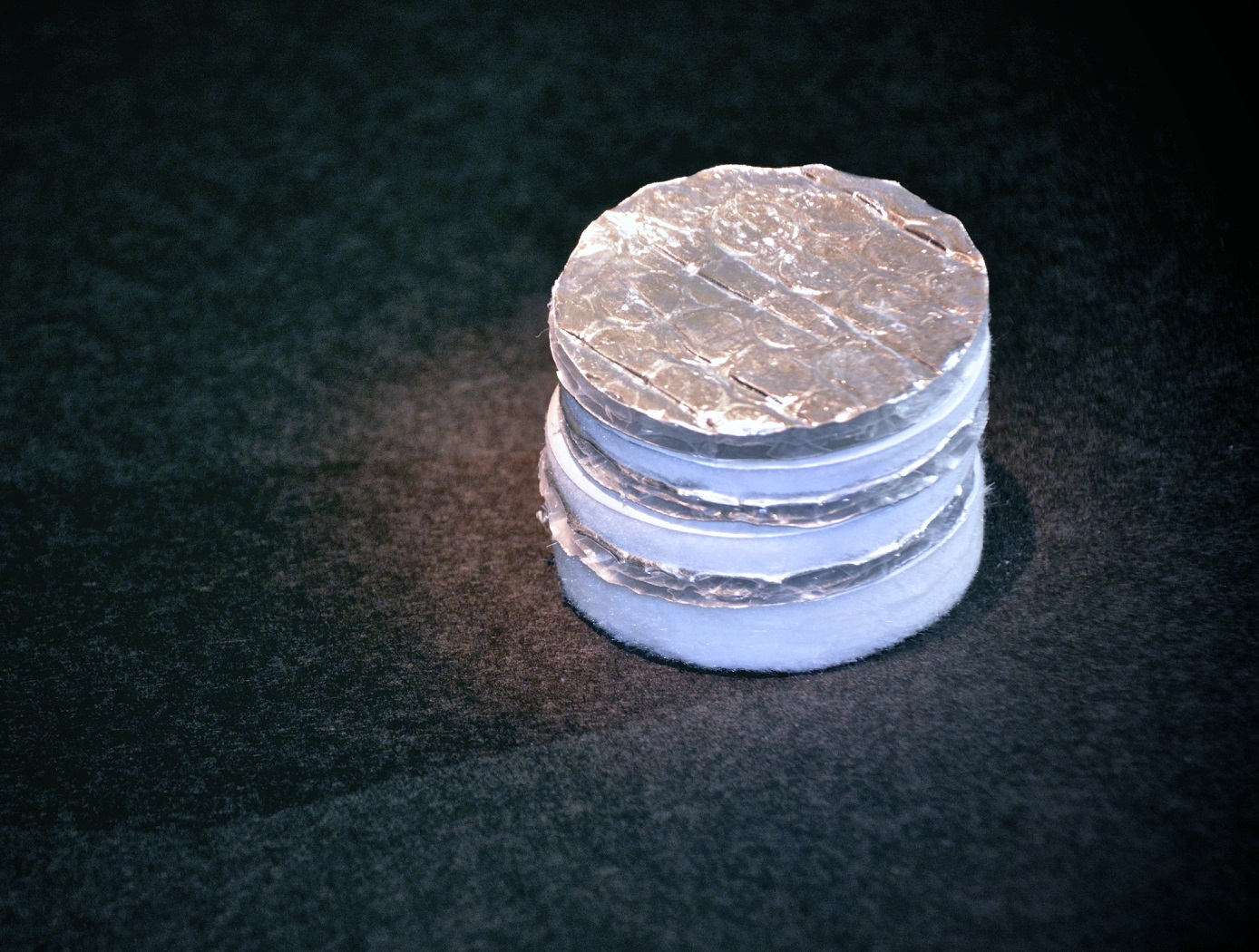
Advanced Materials for Electronics Insulation
Many researchers have attempted to use polymer-ceramic composites to improve the thermal and dielectric performance of polymer insulation for high voltage, high temperature electronics. However, using composite materials has been challenging due to manufacturing issues like incomplete mixing, inhomogeneous properties, and void formation. Here, NASA has developed a method of preparing and extruding polymer-ceramic composites that results in high-quality, flexible composite ribbons.
To achieve this, pellets of a thermoplastic (e.g., polyphenylsulfone or PPSU) are coated with an additive then mixed with particles of a ceramic (e.g., boron nitride or BN) as shown in the image below. After mixing the coated polymer with the ceramic particles, the blended material was processed into ribbons or films by twin-screw extrusion. The resulting ribbons are highly flexible, well-mixed, and void free, enabled by the coated additive and by using a particle mixture of micronized BN and nanoparticles of hexagonal BN (hBN).
The polymer-ceramic composite showed tunable dielectric and thermal properties depending on the exact processing method and composite makeup. Compared to the base polymer material, the composite ribbons showed comparable or improved dielectric properties and enhanced thermal conductivity, allowing the composite to be used as electrical insulation in high-power, high-temperature conditions.
The related patent is now available to license. Please note that NASA does not manufacturer products itself for commercial sale.

