In Situ Wire Damage Detection and Rerouting System
Electrical and Electronics
In Situ Wire Damage Detection and Rerouting System (KSC-TOPS-6)
A miniaturized and highly efficient wire damage detection system
Overview
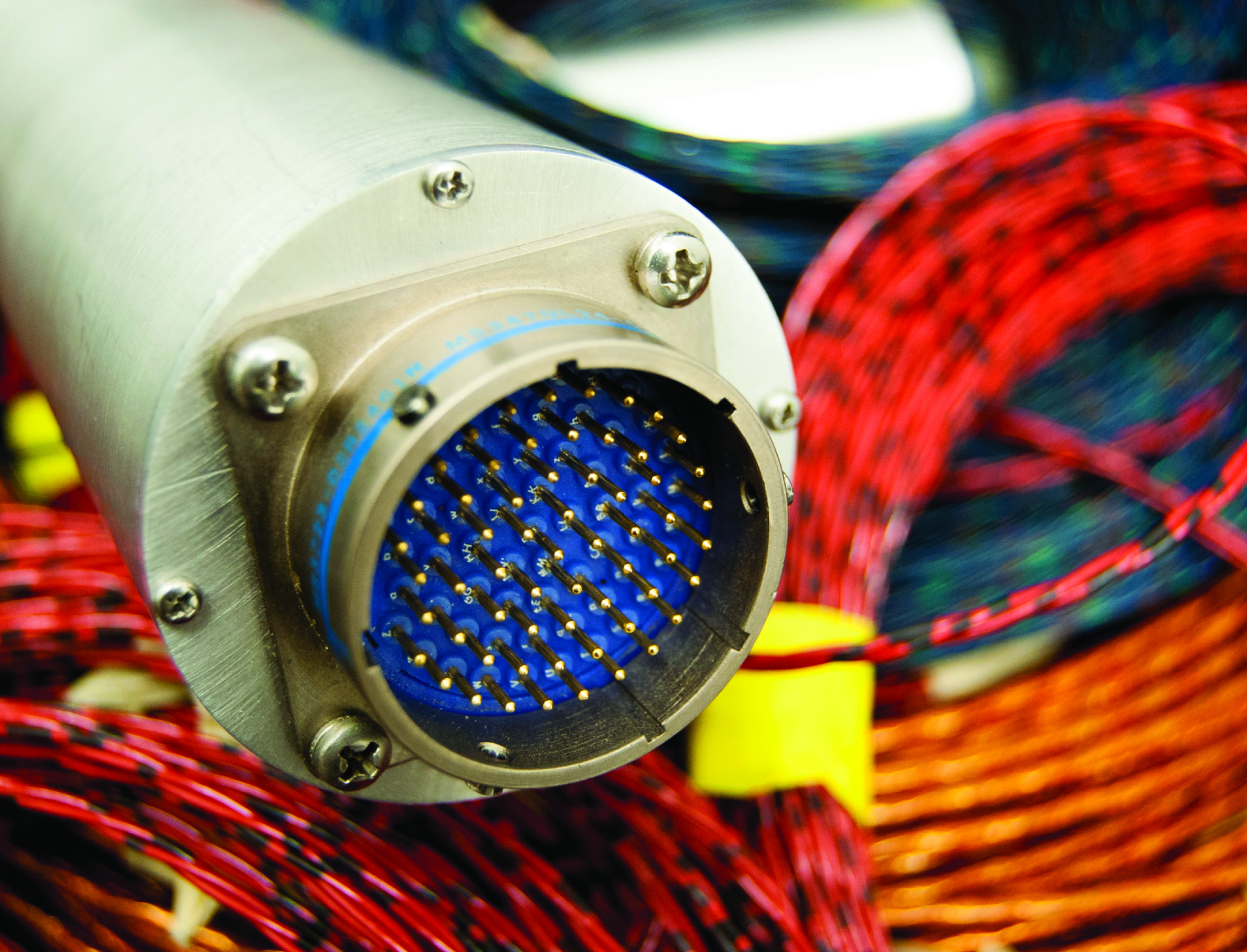
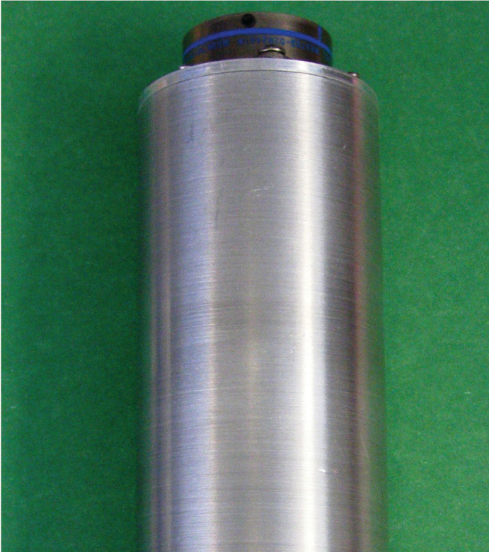
NASA Kennedy Space Center seeks partners interested in the commercial application of the In Situ Wire Damage Detection and Rerouting System. NASA is soliciting licensees for this innovative technology. The In Situ Wire Damage Detection and Rerouting System consists of a miniaturized inline connector containing self-monitoring electronics that use time domain reflectometry (TDR) to detect wire faults and determine fault type and fault location on powered electrical wiring. When a damaged or defective wire is identified, the system is capable of autonomously transferring electrical power and data connectivity to an alternate wire path. When used in conjunction with NASAs wire constructions that use a conductive detection layer, the system is capable of detecting and limiting damage not only to the core conductor, but also to the insulation layer before the core conductor becomes compromised.
The Technology
The tester was designed to monitor electrical faults in either online or offline modes of operation. In the online mode, wires are monitored without disturbing their normal operation. A cable can be monitored several times per second in the offline mode, and once per second in the online mode. The online cable fault locator not only detects the occurrence of a fault, but also determines the type of fault (short/open/intermittent) and the location of the fault. This enables the detection of intermittent faults that can be repaired before they become serious problems. Since intermittent faults occur mainly during operations, a built-in memory device stores all relevant fault data. This data can be displayed in real time or retrieved later so maintenance and repairs can be completed without spending countless hours attempting to pinpoint the source of the problem.
Hardware and algorithms have also been developed to safely, efficiently, and autonomously transfer electrical power and data connectivity from an identified damaged/defective wire in a cable to an alternate wire path. This portion of the system consists of master and slave units that provide the diagnostic and rerouting capabilities. A test pulse generated by the master unit is sent down an active wire being monitored by the slave unit. When the slave unit detects the test pulse, it routes the pulse back to the master unit through a communication wire. When the master unit determines that a test pulse is not being returned, it designates that wire as faulty and reroutes the circuit to a spare wire.


Benefits
- Online operation - system can be used while wires are powered and operational, making it possible to locate intermittent faults that occur only while wires are in use
- Nonintrusive - faults are monitored in the background, using very low power signals that do not disrupt normal circuit operation
- Intelligent - pattern recognition algorithms autonomously identify the type and location of a fault without operator intervention
- Intuitive - an easy-to-understand graphical user interface displays the reflected waveforms and provides information on the type of fault and its distance fromthe test signal injection point
- Flexible - system is capable of monitoring up to 64 individual wires on a cable
- Simultaneously in online or offline mode
Applications
- Aerospace wiring
- Marine wiring
- Automotive wiring
- Industrial wiring
- Smart grid wiring
Similar Results

Damage and Tamper Detection Sensor System
The SansEC sensor system consists of multiple pairs of inductor-capacitor sensors with no electrical connections, which are placed throughout the material being monitored for damage. The sensors are embedded in or placed directly onto the surface of the material. Strains and breaks are detected by changes in resonant frequency read by the accompanying magnetic field data acquisition system. When pulsed by a sequence of magnetic field harmonics from the acquisition system, the sensors become electrically active and emit a wireless response. The magnetic field response attributes of frequency, amplitude, and bandwidth of the inductor correspond to the physical property states measured by the sensor. The received response is correlated to calibration data to determine the physical property measurement. Because each sensor pair has its own frequency response, when damage occurs to that circuit the frequency response changes. This change identifies the damage location within the material.
A unique feature achieved by eliminating electrical connections is that damage to a single point will not prevent the sensor from being powered or interrogated. If a sensor is broken, two concentric inductively coupled sensors are created, thus identifying tamper or damage location.

Wireless Electrical Devices Using Floating Electrodes
The technology presents a fundamental change in the way electrical devices are designed, using an open circuit in conjunction with a floating electrode, or an electrically conductive object not connected to anything by wires, and powered through a wireless device. This system uses inductor-capacitor thin-film open circuit technology. It consists of a uniquely designed, electrically conductive geometric pattern that stores energy in both electric and magnetic fields, along with a floating electrode in proximity to the open circuit. When wirelessly pulsed from the handheld data acquisition system (U.S. Patent Number 7,159,774, Magnetic Field Response Measurement Acquisition System), the system becomes electrically active and develops a capacitance between the two circuit surfaces. The result is a device that acts as a parallel plate capacitor without electrical connections.

Cord Tension Measurement Device (C-Gauge)
The C-Gauge is made of a 3D-printed aluminum body with strain gauges attached to the inner and outer walls of the connecting beam. The legs of the gauge attach firmly to the cord. When the cord is stretched, the tension in the cord goes through the legs and into the beam, causing it to bend. This bending creates a tension and compression stress in the bottom and top surface of the beam, respectively. The strain gauges capture the tension and compression, which are then used to determine the tension in the cord. The use of multiple strain gauges mitigates any torsion loading of the gauge and provides a direct measurement of the axial tension load of the cord.
The C-Gauge is a low-profile, non-invasive system that can be installed onto an existing cord in a system (e.g., the suspension, reefing, or riser lines in a parachute) without the need to remove or re-install the cord. It is small and lightweight and does not add stiffness or weight to the cord and thus does not affect the dynamics of the parachute or the structural response of the system. The C-Gauge can be scaled to larger and smaller sizes to measure larger and smaller load capabilities, dependent on the cord.
The C-Gauge is at a TRL 4 (component and/or breadboard validation in a laboratory environment) and it is now available for your company to license and develop into a commercial product. Please note that NASA does not manufacture products itself for commercial sale.
MMOD Impact Detection and Location
Multiple strain sensors encoded into one or more optical fibers are affixed to a MMOD shield or structure. The optical fiber(s) is/are connected to a data collection device that records strain data at a frequency sufficient to resolve MMOD impact events. Strain data are processed and presented on a computer display. MMOD impact imparts a transient shock loading to a structure which is manifested as transient strain as the shock wave moves through the structure. MMOD impacts are determined from the time signature of, both, measured strain from multiple sensors on the optical fiber(s) as well as strain resulting from plastic strain induced in the MMOD shield and structure as a consequence of the MMOD impact (for materials exhibiting plastic strain). The array of strain sensors, encoded into one or more optical fibers using Fiber Bragg Grating (FBG) technology, records time varying strain to identify that a strike has occurred and at what time it occurred. Strike location information can be inferred from the residual plastic strain recorded by the multitude of strain sensors in the fiber(s). One or more optical fibers may be used to provide optimal coverage of the area of interest and/or to ensure a sufficient number of strain measurements are provided to accurately characterize the nature of the impact.

Enhancing Fault Isolation and Detection for Electric Powertrains of UAVs
The tool developed through this work merges information from the electric propulsion system design phase with diagnostic tools. Information from the failure mode and effect analysis (FMEA) from the system design phase is embedded within a Bayesian network (BN). Each node in the network can represent either a fault, failure mode, root cause or effect, and the causal relationships between different elements are described through the connecting edges.
This novel approach can help Fault Detection and Isolation (FDI), producing a framework capable of isolating the cause of sub-system level fault and degradation.
This system:
Identifies and quantifies the effects of the identified hazards, the severity and probability of their effects, their root cause, and the likelihood of each cause;
Uses a Bayesian framework for fault detection and isolation (FDI);
Based on the FDI output, estimates health of the faulty component and predicts the remaining useful life (RUL) by also performing uncertainty quantification (UQ);
Identifies potential electric powertrain hazards and performs a functional hazard analysis (FHA) for unmanned aerial vehicles (UAVs)/Urban Air Mobility (UAM) vehicles.
Despite being developed for and demonstrated with an application to an electric UAV, the methodology is generalized and can be implemented in other domains, ranging from manufacturing facilities to various autonomous vehicles.


