Search
PATENT PORTFOLIO
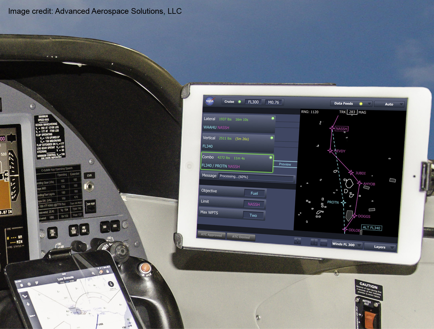
Traffic Aware Strategic Aircrew Requests (TASAR)
The NASA software application developed under the TASAR project is called the Traffic Aware Planner (TAP). TAP automatically monitors for flight optimization opportunities in the form of lateral and/or vertical trajectory changes. Surveillance data of nearby aircraft, using ADS-B IN technology, are processed to evaluate and avoid possible conflicts resulting from requested changes in the trajectory. TAP also leverages real-time connectivity to external information sources, if available, of operational data relating to winds, weather, restricted airspace, etc., to produce the most acceptable and beneficial trajectory-change solutions available at the time. The software application is designed for installation on low-cost Electronic Flight Bags that provide read-only access to avionics data. The user interface is also compatible with the popular iPad. FAA certification and operational approval requirements are expected to be minimal for this non-safety-critical flight-efficiency application, reducing implementation cost and accelerating adoption by the airspace user community.
Awarded "2016 NASA Software of the Year"
System for In-situ Defect Detection in Composites During Cure
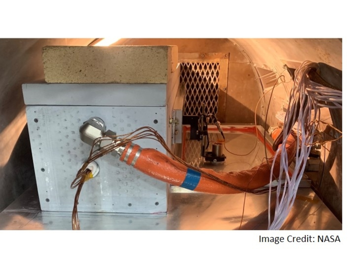
NASA's System for In-situ Defect (e.g., porosity, fiber waviness) Detection in Composites During Cure consists of an ultrasonic portable automated C-Scan system with an attached ultrasonic contact probe. This scanner is placed inside of an insulated vessel that protects the temperature-sensitive components of the scanner. A liquid nitrogen cooling systems keeps the interior of the vessel below 38°C. A motorized X-Y raster scanner is mounted inside an unsealed cooling container made of porous insulation boards with a cantilever scanning arm protruding out of the cooling container through a slot. The cooling container that houses the X-Y raster scanner is periodically cooled using a liquid nitrogen (LN2) delivery system. Flexible bellows in the slot opening of the box minimize heat transfer between the box and the external autoclave environment. The box and scanning arm are located on a precision cast tool plate. A thin layer of ultrasonic couplant is placed between the transducer and the tool plate. The composite parts are vacuum bagged on the other side of the tool plate and inspected. The scanning system inside of the vessel is connected to the controller outside of the autoclave. The system can provide A-scan, B-scan, and C-scan images of the composite panel at multiple times during the cure process.
The in-situ system provides higher resolution data to find, characterize, and track defects during cure better than other cure monitoring techniques. In addition, this system also shows the through-thickness location of any composite manufacturing defects during cure with real-time localization and tracking. This has been demonstrated for both intentionally introduced porosity (i.e., trapped during layup) as well processing induced porosity (e.g., resulting from uneven pressure distribution on a part). The technology can be used as a non-destructive evaluation system when making composite parts in in an oven or an autoclave, including thermosets, thermoplastics, composite laminates, high-temperature resins, and ceramics.
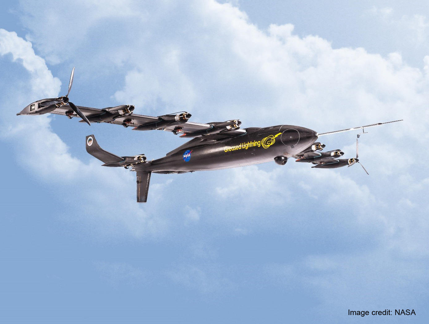
VTOL UAV With the Cruise Efficiency of a Conventional Fixed Wing UAV
The core technology that enables the Greased Lightning UAV is the aerodynamic efficiency it achieves in its cruise configuration. Electric motors at each propeller negate the need for drive shafts and gearing which enables this Distributed Electric Propulsion (DEP) aircraft configuration. The design is intended to utilize a hybrid electric drive system that includes small diesel engines which drive alternators to power the electric motors and to charge an on-board battery system. The batteries provide the power boost needed for VTOL and hovering. Numerous other novel design elements are incorporated, such as folding propellers to minimize drag when not in operation, such that the propulsive efficiency can be nearly ideal at both hover and wing borne flight conditions.

Optical Head-Mounted Display System for Laser Safety Eyewear
The system combines laser goggles with an optical head-mounted display that displays a real-time video camera image of a laser beam. Users are able to visualize the laser beam while his/her eyes are protected. The system also allows for numerous additional features in the optical head mounted display such as digital zoom, overlays of additional information such as power meter data, Bluetooth wireless interface, digital overlays of beam location and others. The system is built on readily available components and can be used with existing laser eyewear. The software converts the color being observed to another color that transmits through the goggles. For example, if a red laser is being used and red-blocking glasses are worn, the software can convert red to blue, which is readily transmitted through the laser eyewear. Similarly, color video can be converted to black-and-white to transmit through the eyewear.

Reliable Geo-Limitation Algorithm for Unmanned Aircraft
Safeguard is an independent avionics equipment that can be easily ported to virtually any UA. The current prototype weighs approximately 1 lb (without hardware optimization). The invention innovations include formally verified algorithms to monitor and predict impending boundary violations through flight termination trajectory estimation. A system could be configured without sole reliance on the GPS to avoid known problems with GPS inaccuracies and unavailability. It can operate independent of the UA and any on-board components, such as the autopilot, for physical and logical separation from non-aviation-grade systems. The perimeter boundaries are described using polygons, which can approximate almost any shape, and there are practically no limits to the number of shapes and boundaries. The algorithms for establishing the validity of a boundary and for detecting proximity to all defined boundaries are based on rigorous mathematical models that have been formally verified.
Software required to operate cannot be licensed from NASA, the licensee must create and/or procure separately.
Reflection-Reducing Imaging System for Machine Vision Applications
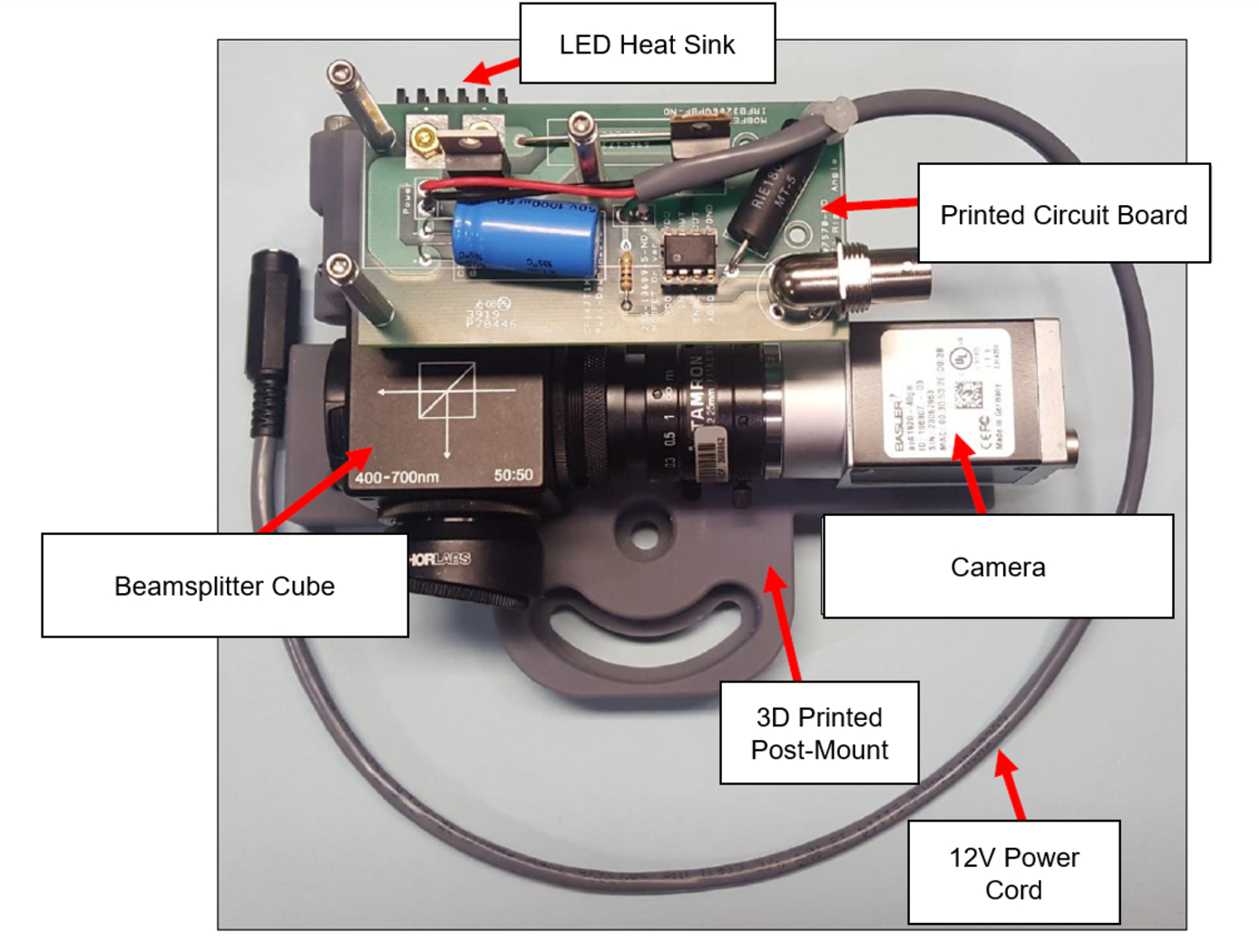
NASA’s imaging system is comprised of a small CMOS camera fitted with a C-mount lens affixed to a 3D-printed mount. Light from the high-intensity LED is passed through a lens that both diffuses and collimates the LED output, and this light is coupled onto the cameras optical axis using a 50:50 beam-splitting prism.
Use of the collimating/diffusing lens to condition the LED output provides for an illumination source that is of similar diameter to the camera’s imaging lens. This is the feature that reduces or eliminates shadows that would otherwise be projected onto the subject plane as a result of refractive index variations in the imaged volume. By coupling the light from the LED unit onto the camera’s optical axis, reflections from windows – which are often present in wind tunnel facilities to allow for direct views of a test section – can be minimized or eliminated when the camera is placed at a small angle of incidence relative to the window’s surface. This effect is demonstrated in the image on the bottom left of the page.
Eight imaging systems were fabricated and used for capturing background oriented schlieren (BOS) measurements of flow from a heat gun in the 11-by-11-foot test section of the NASA Ames Unitary Plan Wind Tunnel (see test setup on right). Two additional camera systems (not pictured) captured photogrammetry measurements.
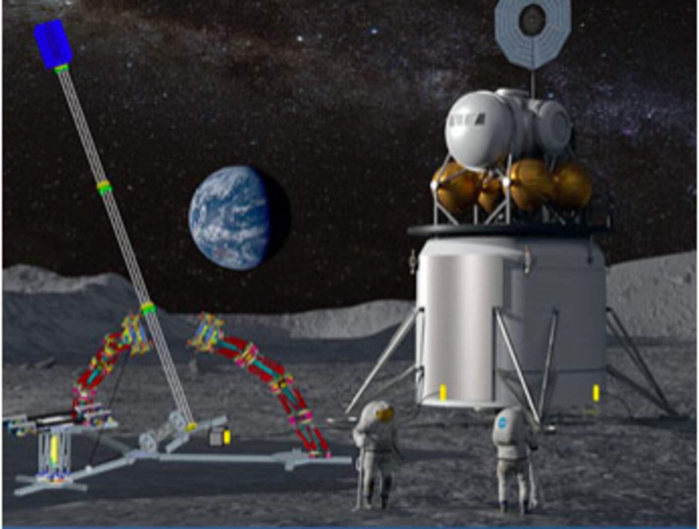
Assemblers
Assemblers are a team of modular robots that work together to build things. Each Assembler is a stack of one or more Stewart platforms, or hexapods, made up of two plates connected by six linear actuators for movement, enabling a full six-degree-of-freedom (DOF) pose of the top plate relative to the bottom plate (see figure to the right). An end effector on each Assembler enables gripping, lifting, and welding/joining. The Assemblers system architecture features novel control algorithms and software, sensors, and communicator technology that coordinate operations of Assembler teams. The control system includes an important module for task management that estimates how many robots are needed, the optimal number of hexapods in each Assembler, and the estimated voltage needed. There are also modules for trajectory generation, joint control, sensor fusion, and fault detection. The novel control system directs the Assembler operations for high accuracy and precision, yet there is built-in dynamic resilience to failure. For example, if a single hexapod on an Assembler fails, the system deems it “rigid” in its last pose and redistributes the work to the other Assemblers.
The image below shows a storyboard of operations for how Assemblers might build a solar array. NASA has developed a hardware demo with communications between subsystems, backed up by detailed simulations of the kinematics and actuator dynamics.

Electroactive Material for Wound Healing
An electroactive device is applied to an external wound site. This method utilizes generated low level electrical stimulation to promote the wound healing process while simultaneously protecting it from infection. The material is fabricated from polyvinylidene fluoride, or PVDF, a thermoplastic fluoropolymer that is highly piezoelectric when poled. The fabrication method of the electroactive material is based on a previous Langley invention of an apparatus that is used to electrospin highly aligned polymer fiber material. A description of the fabrication method can be found in the technology opportunity announcement titled "NASA Langley's Highly Electrospun Fibers and Mats," which is available on NASA Langley's Technology Gateway.
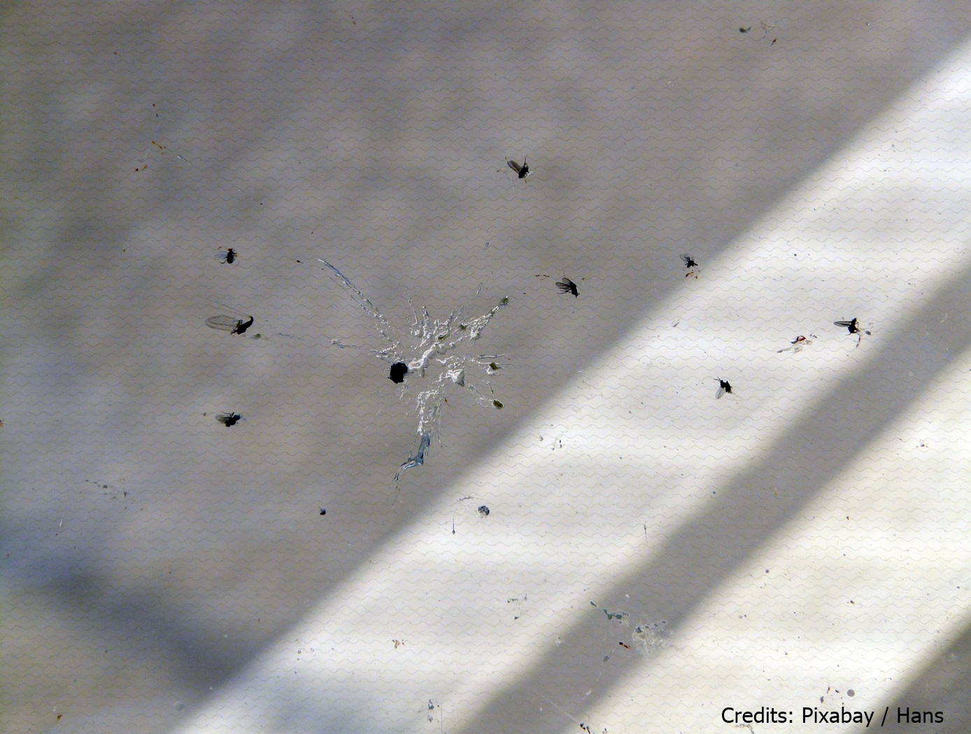
Hydrophobic Epoxy Coating for Insect Adhesion Mitigation
This technology is a copolymeric epoxy coating that is loaded with a fluorinated aliphatic chemical species and nano- to microscale particle fillers. The coating was developed as a hydrophobic and non-wetting coating for aerodynamic surfaces to prevent accumulation of insect strike remains that can lead to natural laminar flow disruption and aerodynamic inefficiencies. The coating achieves hydrophobicity in two ways. First, the fluorinated aliphatic chemical species are hydrophobic surface modification additives that preferentially migrate to the polymer surface that is exposed to air. Secondly, the incorporation of particle fillers produces a micro-textured surface that displays excellent resistance to wetting. Combined, these two factors increase hydrophobicity and can also be used to readily generate superhydrophobic surfaces.
View more patents

