Search
PATENT PORTFOLIO

HYPERFIRE
In order to maintain the low cost, simplicity, and quick turnaround of cold-flow testing while improving accuracy, NASA evaluated unconventional gases for use as simulants. During such evaluations, NASA discovered that by adjusting stagnation temperature, the isentropic exponent of ethane can be tuned to approximate those of common rocket propellants (e.g., hydrogen, hypergols, alcohols, and hydrocarbons). Furthermore, due to ethanes high auto-ignition temperature and resistance to condensation, tuned ethane enables testing of expansion ratios much larger than conventional inert-gas testing.
To leverage this discovery, NASA developed a hardware-based system to treat ethane and obtain nozzle chamber conditions that match the appropriate aerodynamics for a specific test. The system, named HYPERFIRE, works in the following manner. Liquid ethane is transferred to a piston-style run tank, where it is pressurized. Then, the ethane is run through two insulated pebble beds where it is heated, vaporized, and stabilized. Finally, the treated ethane is transferred from the second pebble bed to a small thrust takeout structure, and through the test article. Control of valves and regulators is managed by an onboard computer, accessed via a LabVIEW™ interface. The system is mounted on a hurricane-resistant steel frame to enable transportation via forklift.
Heated ethane reproduces the aerodynamics of combustion products at low temperatures relative to alternative testing methods. Thus, test articles can be manufactured using low-cost, low temperature rated, transparent materials (e.g., acrylic). In addition to reducing testing cost, this grants optical access to internal flowfields, enabling advanced diagnostic techniques (e.g., Schlieren imaging, particle image velocimetry) not possible with hot-fire testing and less meaningful with conventional cold-flow testing.
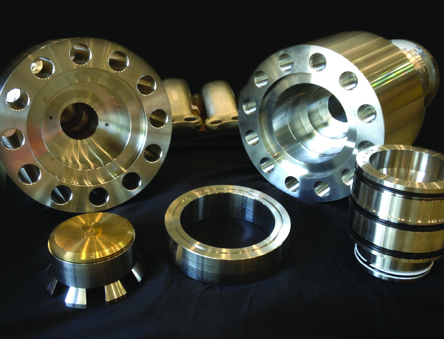
Floating Piston Valve
Instead of looking to improve current valve designs, a new type of valve was conceived that not only addresses recurring failures but could operate at very high pressures and flow rates, while maintaining high reliability and longevity. The valve design is applicable for pressures ranging from 15-15,000+ psi, and incorporates a floating piston design, used for controlling a flow of a pressurized working fluid.
The balanced, floating piston valve design has a wide range of potential applications in all sizes and pressure ranges. The extremely simple design and few parts makes the design inherently reliable, simple to manufacture, and easy to maintain. The valve concept works with soft or hard metal seats, and the closing force is easily adjustable so that any closing force desired can be created. The fact that no adjustment is required in the design, ensures valve performance throughout valve life and operation.
This valve has many unique features and design advantages over conventional valve concepts:
- The largest advantage is the elimination of the valve stem and any conventional actuator, reduces physical size and cost.
- It is constructed with only 5 parts.
- It eliminates the need for many seals, which reduces failure, downtime and maintenance while increasing reliability and seat life.
- The flow path is always axially and radially symmetric, eliminating almost all of the flow induced thrust loads - even during transition from closed to open.
In Situ Performance Monitoring of Piezoelectric Sensors and Accelerometers
On occasion, anomalies may appear in the highly dynamic test data obtained during rocket engine tests, which are investigated and corrective action may be mandated before subsequent testing. Also, it is often unclear if anomalies in recorded signals are due to differences between the Low and High Speed Data Acquisitions Systems, difference between the transducers, a failed transducer, or if everything is working correctly and the system were actually accurately recording real events. Commercial test equipment suitable for testing piezoelectric sensors is expensive and requires that the sensor be removed from the test article for evaluation. With the monitoring system developed, degraded sensor performance can be quickly and economically identified.
This system can evaluate installed piezoelectric sensors, without requiring physical contact with or removing them from their mounted locations. Tests are conducted through cabling. Since it is not necessary to remove the device, data that reflect the devices specific physical configuration (such as as-mounted resonant frequency) are retained, and devices that are physically inaccessible can still be tested. The testing system is not limited to identifying degraded performance in the sensors piezoelectric elements; it can detect changes within the entire sensor, and sensor housing.
The system can be made portable, in a battery powered sealed box, for testing in the field. Since physical contact with the sensor is not necessary, therefore, monitoring can be done as far away as 250 feet, or longer if certain provisions are made.
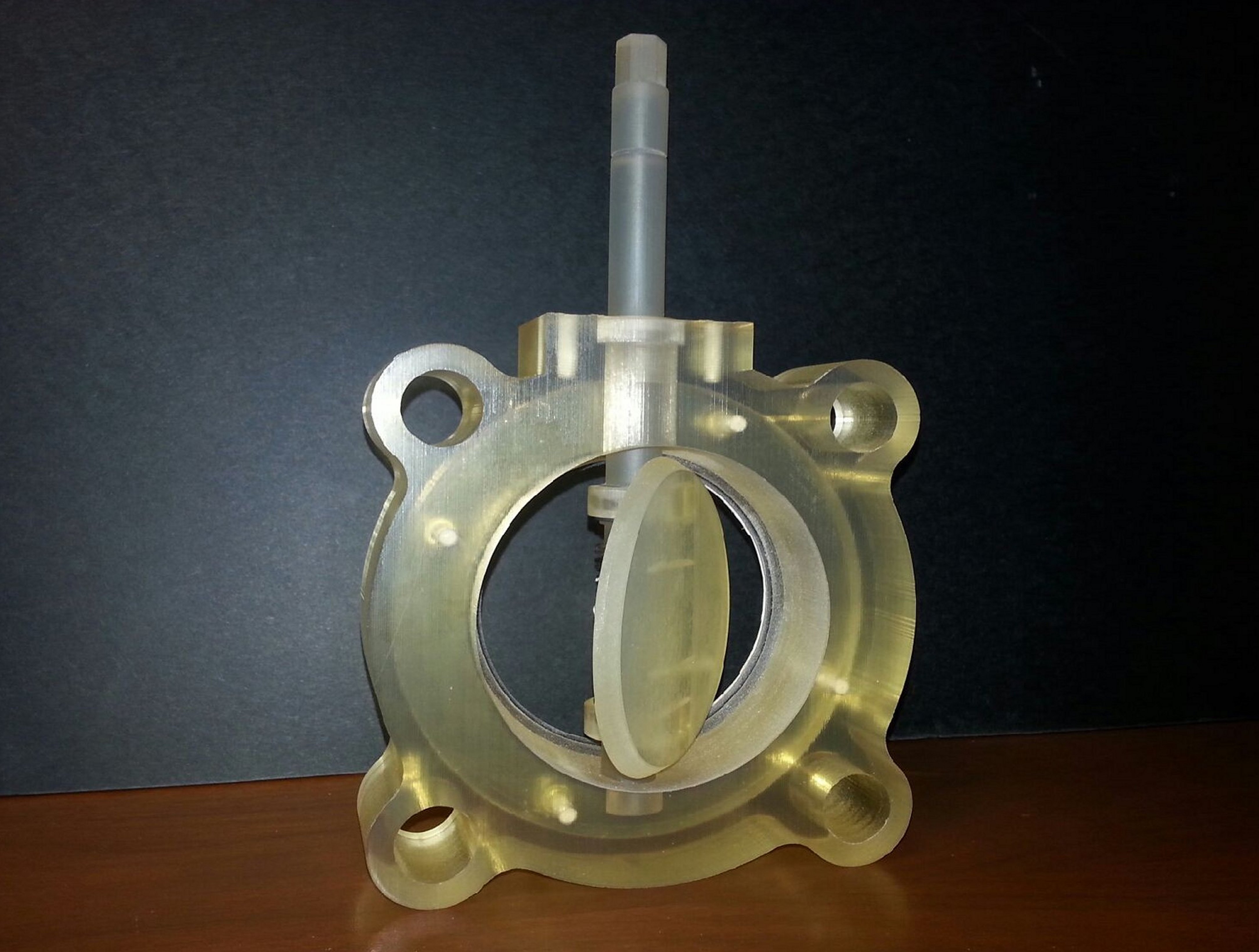
Cryogenic Cam Butterfly Valve
A globe valve controls flow by translating a disc over an opening. A butterfly valve controls flow by rotating a disc in an opening. The disc and seat of a butterfly valve have to create a tight seal exactly when the disc meets the 90 degree mark. If additional torque (energy) is added to the actuator of a butterfly valve, the disc will rotate past 90 degrees and the valve will open again. Therefore, with a standard butterfly valve, additional actuator energy cannot be added to reduce or minimize seat leakage, like with a globe valve.
The novel Cryogenic Cam Butterfly Valve (CCBV) design functions like a typical butterfly valve, rotated to open or close the valve. However, unlike a typical butterfly valve disc that can only rotate, the CCBV can be translated and rotated to control flow. The main parts of the CCBV include a body, disc, cam shaft, torsion spring and 180 degree actuator. In the full open position, disc rotation is 0 degrees and the disc is approximately perpendicular to the valve body to enable maximum flow. However, unlike a typical butterfly valve where the disc is not pinned to the shaft, the CCBV has a preloaded torsion spring mounted concentrically on the shaft with the spring legs against the disc, and a pin to keep the disc coupled to the shaft. The torsion spring is preloaded with sufficient torque so that the disc/shaft assembly acts like the disc is rigidly pinned to the shaft. The first 90 degrees of the actuator and shaft rotation rotates the disc, just like a typical butterfly valve; however, at approximately 90 degrees, one edge of the disc makes contact with the body seat, while the opposite edge is slightly off of the body seat. At this point, the disc can no longer rotate. The cam shaft then converts rotatory motion into translational motion. Because of the cam shaft lobes, as the actuator continues to rotate the shaft, the disc can now translate towards the body, and enables more of the disc to seal against the body seat. Therefore, all actuator and shaft rotation beyond 90 degrees translates the disc towards the body seat to create a tighter seal, similar to how globe valve functions. When the valve is in this position, seat leakage will be reduced and with additional actuator rotation, stopped. Eventually, a tight seal is formed in the full closed position. Then, with opposite shaft rotation, the valve will open. The CCBV incorporated the advantages of a globe to achieve tight seals from ambient to cryogenic temperatures.
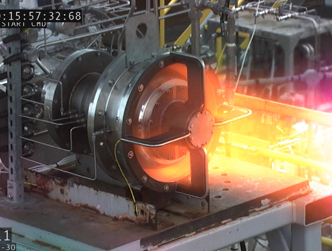
Supersonic Spike Diffuser
The basic mode of operation for all passive supersonic diffusers is to enable a plume’s inherent power to drive the outer boundary of the exhaust jet to the diffuser wall so that the entire cross-section of the flow has a speed greater than that of sound. This allows mass removal from the area surrounding the nozzle via entrainment. The result is a low-pressure environment similar to the altitude at which the nozzle was designed to operate. Additionally, the nature of supersonic flow prevents pressure interference from the downstream environment.
The specific geometry of each coupled nozzle-diffuser system dictates how efficiently it is able to operate, with the primary indicator of performance being the stagnation-to-ambient pressure ratio at which the plume attaches to the wall and “starts” the diffuser. Cylindrical diffusers simply provide a surface for plume attachment and have the worst performance of all geometries but are easy to construct. Second-throat diffusers are characterized by an additional area contraction which provides better resistance to ambient backpressure. Centerbody diffusers reduce shock losses by placing an aerodynamic obstruction in a cylindrical diffuser to prevent high Mach number plume expansion. They provide the best performance and smallest physical envelope of historically-used diffuser types. Spike diffusers are unconventional by comparison and are characterized by the use of an aerodynamic centerbody which expands beyond the diameter of the rocket itself, reducing high Mach number losses and a single turning of the entire core flow so that its velocity has a strong radial component. Additionally, they feature contouring of the surrounding aeroshell in a manner that provides an axial area ratio profile similar to that of second throat diffusers. By combining desirable aspects of the conventional diffuser types, they are able to provide the best overall aerodynamic performance in the smallest spatial envelope.

