Search
PATENT PORTFOLIO
Robotics, Automation and Control
From autonomous robots and drones to advanced control systems and machine learning algorithms, NASA's robotics, automation, and control technology offers a range of options for automating and improving the performance of systems and processes. Whether you're looking to develop new robotics technologies or to improve the efficiency of your manufacturing operations, NASA's might have a solution to help you reach your goals.

Visual Inspection Posable Invertebrate Robot (VIPIR)
Initially developed as a close quarters inspection tool capable of accessing hard to reach, tight, or visibly restricted, areas of satellites, the VIPIR system can be used to remotely inspect inaccessible locations such as behind a sheet of thermal blanketing material, into a satellites plumbing, or perhaps even deep inside the otherwise unreachable crevasses of a spacecraft bus. The VIPIR system incorporates a number of subassemblies for incredible operational freedom and capabilities for imaging and dissemination of componentry.
VIPIR’s Video Borescope Assembly (VBA) is a flexible snake-camera capable of multidirectional articulations, making steering and control simple and intuitive for an operator. The VBA also includes at least one imaging sensor and lighting to see in dark, confined spaces. Real-time, high-resolution visual information can be fed back to an operator for live analysis. A reel system extends and retracts the VBA with the use of a spool, and includes position indicators for deployment tracking. The Tendon Management System (TMS), not unlike human tendons, utilizes pulleys and tensioners to articulate the VBA in the confined spaces. A seal system ensures the VBA is free of contamination.
VIPIR underwent space-based testing on the ISS during the Robotic Refueling Phase 2 (RRM-2) mission designed to showcase and test several NASA advanced robotic satellite servicing technologies. During this mission, VIPIR demonstrated state-of-the-art near and midrange inspection capabilities. NASA’s VIPIR system is available for licensing to industry, and may be desirable to companies focused on satellite servicing, on-orbit assembly, and other applications requiring detailed inspection of assets in space.

Robotic System for Infra-structure Reconnaissance
The robotic system is comprised of six main components: the orb that performs the reconnaissance, an orb injector housing that attaches to a piping network, a tether and reel subsystem that attaches to the back of the injector housing, a fluid injection subsystem that attaches toward the front of the injector housing, an external power and data subsystem, and associated control and monitoring software.
Usage of the system begins with an operator attaching the injector housing, with the orb stowed inside, to a flanged gate valve belonging to the piping network of concern. Requisite power, data, and fluid subsystems are attached, and the system is energized for usage. The orb is released via the tether and reel, and a controlled fluid force is imparted on the orb to help guide it along its mission. The tether supplies power and guidance to the orb, and relays real-time data back to the operator.
The orb’s interior features a modular plug-and-play architecture which may comprise COTS instrumentation for reconnaissance or investiga-tion, LIDAR, and inertial measuring and motion sensors. This instru-mentation could be used in combination with other sub-systems such as lighting, and core and sample retrieving mechanisms. These com-ponents are supported by other onboard devices such as a CPU, power source and controller, and data transmission encoders and multiplexers.
The Robotic System for Infrastructure Reconnaissance is at TRL 8 (actual system completed and "flight qualified" through test and demonstration), and is now available for licensing. Please note that NASA does not manufacture products itself for commercial sale.

Robo-Glove
Originally developed by NASA and GM, the Robo-Glove technology was a spinoff of the Robonaut 2 (R2), the first humanoid robot in space. This wearable device allows the user to tightly grip tools and other items for longer periods of time without experiencing muscle discomfort or strain. An astronaut working in a pressurized suit outside the space station or an assembly operator in a factory might need to use 15 to 20 lbs of force to hold a tool during an operation. Use of the Robo-Glove, however, would potentially reduce the applied force to only 5 to 10 lbs.
The Robo-Glove is a self-contained unit, essentially a robot on your hand, with actuators embedded into the glove that provide grasping support to human fingers. The pressure sensors, similar to the sensors that give R2 its sense of touch, are incorporated into the fingertips of the glove to detect when the user is grasping an object. When the user grasps the object, the synthetic tendons automatically retract, pulling the fingers into a gripping position and holding them there until the sensor is released by releasing the object. The current prototype weighs around two pounds, including control electronics and a small display for programming and diagnostics. A lithium-ion battery, such as one for power tools, is used to power the system and is worn separately on the belt.
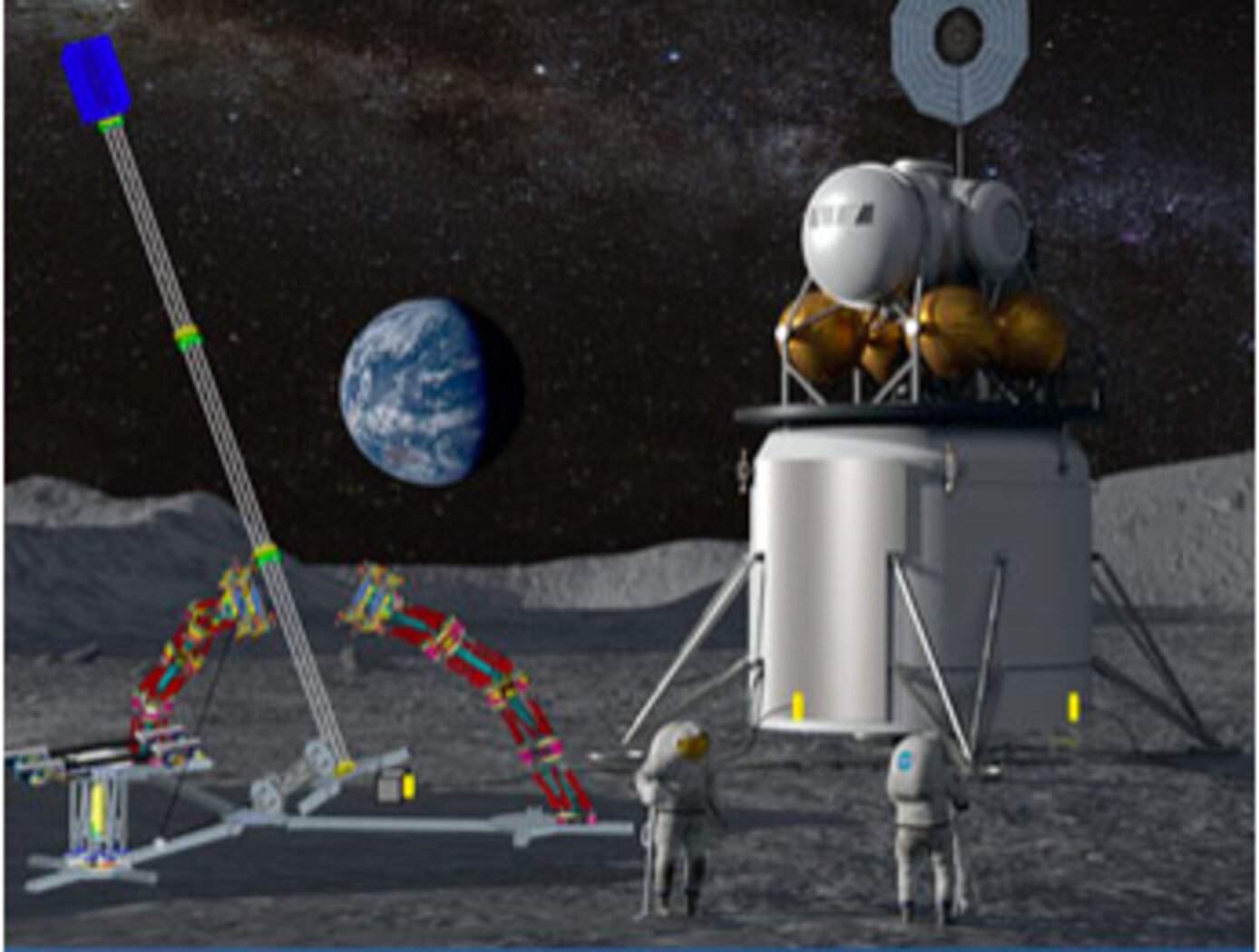
Assemblers
Assemblers are a team of modular robots that work together to build things. Each Assembler is a stack of one or more Stewart platforms, or hexapods, made up of two plates connected by six linear actuators for movement, enabling a full six-degree-of-freedom (DOF) pose of the top plate relative to the bottom plate (see figure to the right). An end effector on each Assembler enables gripping, lifting, and welding/joining. The Assemblers system architecture features novel control algorithms and software, sensors, and communicator technology that coordinate operations of Assembler teams. The control system includes an important module for task management that estimates how many robots are needed, the optimal number of hexapods in each Assembler, and the estimated voltage needed. There are also modules for trajectory generation, joint control, sensor fusion, and fault detection. The novel control system directs the Assembler operations for high accuracy and precision, yet there is built-in dynamic resilience to failure. For example, if a single hexapod on an Assembler fails, the system deems it “rigid” in its last pose and redistributes the work to the other Assemblers.
The image below shows a storyboard of operations for how Assemblers might build a solar array. NASA has developed a hardware demo with communications between subsystems, backed up by detailed simulations of the kinematics and actuator dynamics.
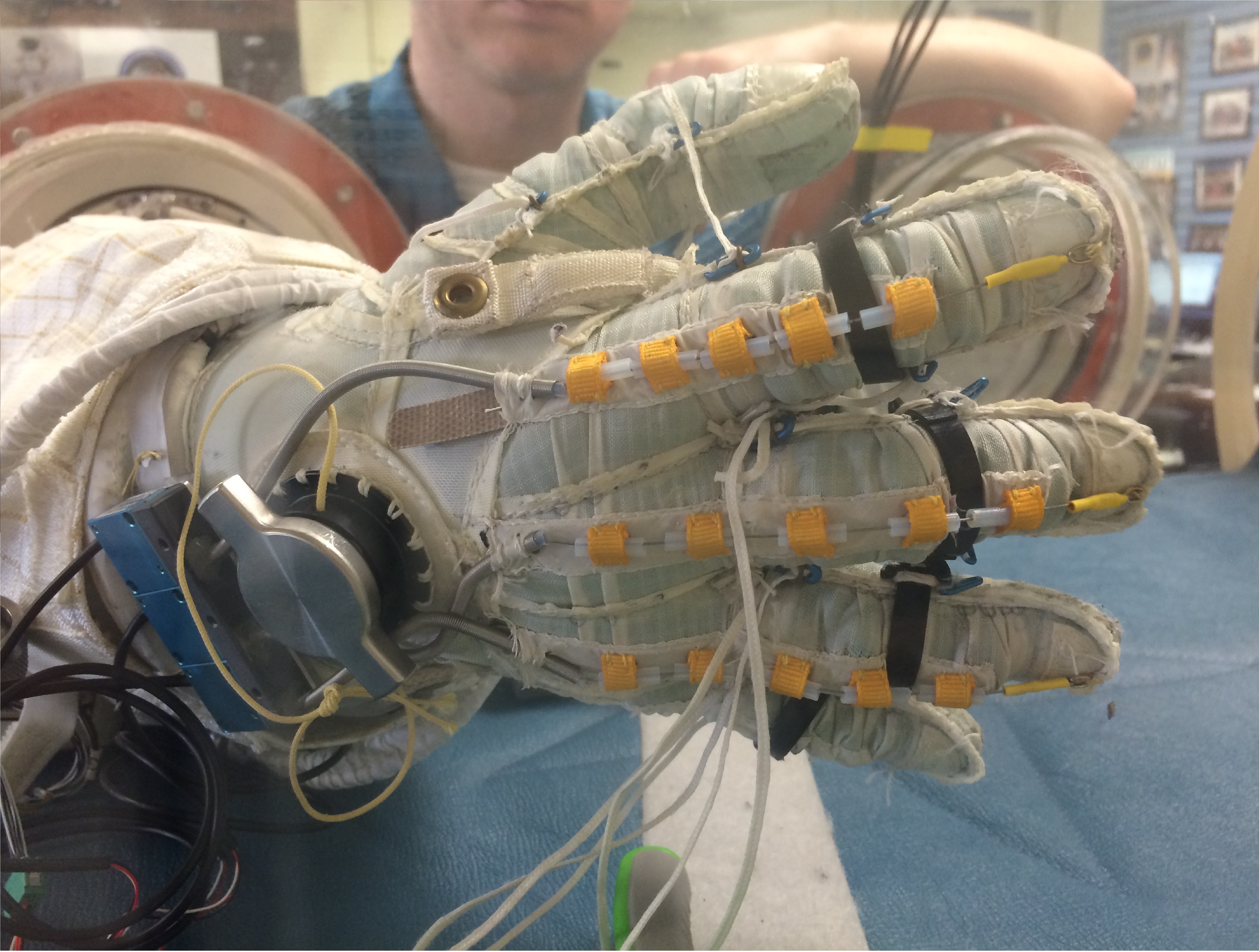
Space Suit RoboGlove (SSRG)
NASA is currently developing the next generation space suit for future missions, including the optimization of space suit gloves. When non-assisted space suit gloves are coupled to a pressurized suit and operated in a vacuum, they tend to limit the range of motion of an astronaut's hand to as little as 20% of normal range. Many of NASA's future missions will be in challenging environments where an astronaut’s hand dexterity will be critical for the success of NASA missions. Innovators at JSC have improved the performance on the second-generation, robotically assisted SSRG, to reduce exertion and improve the hand strength and dexterity of an astronaut in situ.
The SSRG’s system detects user finger movements using string potentiometers and contact with objects using force-sensitive resistors (FSRs). FSRs are imbedded in the distal and medial phalanges, palmar side of the glove. To move a finger, an actuator pulls a tendon through a Bowden Cable system which transfers mechanical pulling force of an inner cable relative to a hollow outer cable, like the brakes on a bicycle, as seen in the Figure below. An improved controller commands the new, more powerful linear actuator to drive tendon operation while minding custom controller parameters inputted through a digital editor tool.
The Space Suit RoboGlove is at TRL 6 (system/subsystem model or prototype demonstrated in a relevant environment) and it is now available for licensing. Please note that NASA does not manufacture products itself for commercial sale.

Anonymous Feature Processing for Enhanced Navigation
This concept presents a new statistical likelihood function and Bayesian analysis update for non-standard measurement types that rely on associations between observed and cataloged features. These measurement types inherently contain non-standard errors that standard techniques, such as the Kalman filter, make no effort to model, and this mismodeling can lead to filter instability and degraded performance.
Vision-based navigation methods utilizing the Kalman filter involve a preprocessing step to identify features within an image by referencing a known catalog. However, errors in this pre-processing can cause navigation failures. AFP offers a new approach, processing points generated by features themselves without requiring identification. Points such as range or bearing are directly processed by AFP.
Operating on finite set statistics principles, AFP treats data as sets rather than individual features. This enables simultaneous tracking of multiple targets without feature labeling. Unlike the sequential processing of the Kalman filter, AFP processes updates in parallel, independently scoring each output based on rigorous mathematical functions. This parallel processing ensures robust navigation updates in dynamic environments, and without requiring an identification algorithm upstream of the filter.
Computational simulations conducted at Johnson Space Center demonstrate that AFP's performance matches or exceeds that of the ideal Kalman filter, even under non-ideal conditions. Anonymous Feature Processing for Enhanced Navigation is at a technology readiness level (TRL) 4 (component and/or breadboard validation in laboratory environment) and is now available for patent licensing. Please note that NASA does not manufacture products itself for commercial sale.
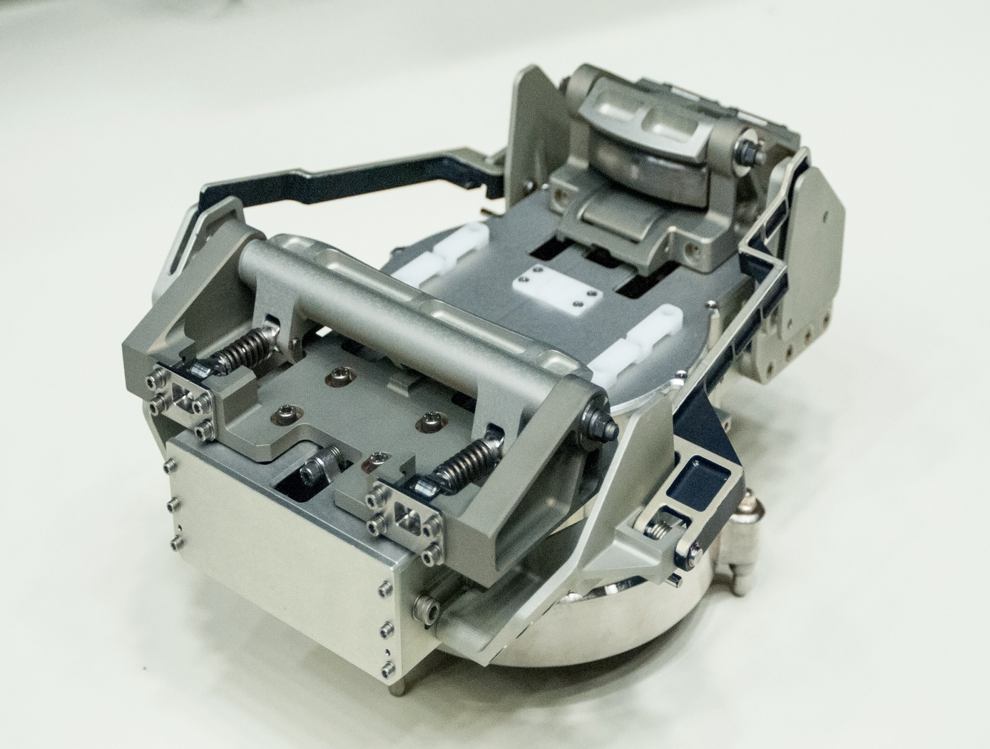
Robotic gripper for satellite capture and servicing
The Gripper is located at the end of a robotic system consisting of a robotic arm equipped with a Tool Drive or End Effector comprising the input actuator to the Gripper as well as the structural, power and data link between the Gripper and the robotic arm. In a notional concept of operations, a Servicer would approach the Client in an autonomous rendezvous and capture (AR&C) maneuver. When the Servicers sensor suite confirms that the distance, orientation, and relative translational and angular rates with respect to the Client are within an acceptable range, the Servicer enables the grasping sequence, where the robotic arm, equipped with Gripper, extend forward to the Client. When the Gripper/ Servicer sensors indicate that the Client marman ring is sufficiently within the capture range of the Gripper, a trigger signal is sent to the robot control system that commands the End Effector to drive the mechanism of the Gripper and affect closure around the marman ring. The Gripper consists of a pair of jaws which are driven by an internal transmission. The transmission receives input torque from the End Effector and converts the torque to appropriate motion of the jaws.
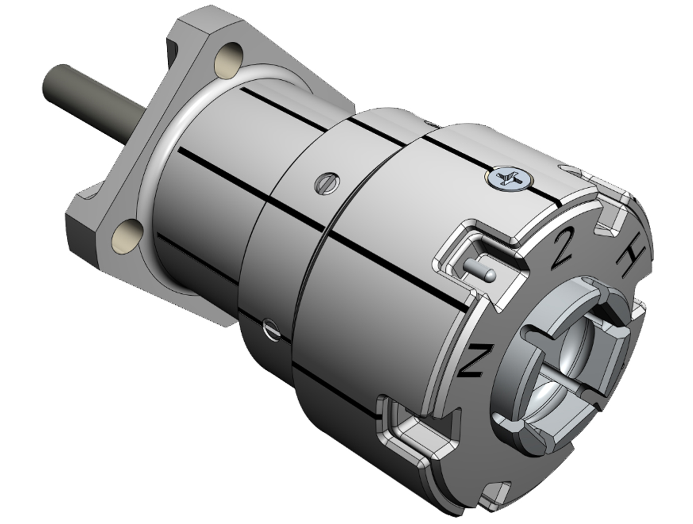
Cooperative Service Valve for In-orbit Cooperative Satellite Fueling
The CSV replaces a standard spacecraft Fill and Drain Valve to facilitate cooperative servicing. The CSV offers various advantages over standard service valves: a robotic interface, three individually actuated seals, a self-contained anti-back drive system, and built-in thermal isolation. When mounted to a spacecraft as designed, the CSV transfers all operational and induced robotic loads to the mounting structure. An anti-back drive mechanism prevents the CSV seal mechanism from inadvertent actuation. Alignment marks, thermal isolation, and a mechanical coupling capable of reacting operational and robotic loads optimize the CSV for tele-robotic operations. Unique keying of the mating interface prevents mixing of media where more than one configuration of the CSV is used. Color-coding and labels are also used to prevent operator error.
The CSV has four configurations for different working fluids, all with essentially unchanged geometry and mechanics.

FlashPose: Range and intensity image-based terrain and vehicle relative pose estimation algorithm
Flashpose is the combination of software written in C and FPGA firmware written in VHDL. It is designed to run under the Linux OS environment in an embedded system or within a custom development application on a Linux workstation. The algorithm is based on the classic Iterative Closest Point (ICP) algorithm originally proposed by Besl and McKay. Basically, the algorithm takes in a range image from a three-dimensional imager, filters and thresholds the image, and converts it to a point cloud in the Cartesian coordinate system. It then minimizes the distances between the point cloud and a model of the target at the origin of the Cartesian frame by manipulating point cloud rotation and translation. This procedure is repeated a number of times for a single image until a predefined mean square error metric is met; at this point the process repeats for a new image.
The rotation and translation operations performed on the point cloud represent an estimate of relative attitude and position, otherwise known as pose.
In addition to 6 degree of freedom (DOF) pose estimation, Flashpose also provides a range and bearing estimate relative to the sensor reference frame. This estimate is based on a simple algorithm that generates a configurable histogram of range information, and analyzes characteristics of the histogram to produce the range and bearing estimate. This can be generated quickly and provides valuable information for seeding the Flashpose ICP algorithm as well as external optical pose algorithms and relative attitude Kalman filters.
View more patents

