Search
materials and coatings

Origami-based Deployable Fiber Reinforced Composites
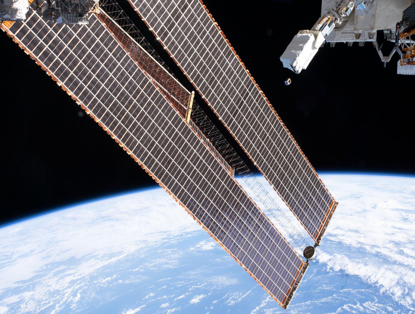
Deployable space structures often rely upon telescoping or folding structures that either must be manually deployed or deployed by attached motors. These structures are often made from heavier (relative to carbon fiber composites) metals to provide enough strength to support a load. As such, there is a need for in-space structures that are lightweight, can be packaged compactly, and can be deployed easily.
The composite material developed here does not require high temperature baking to cure the polymer, rather relying on UV light to solidify the polymer component. The composite is then included into origami-based structures that can fold and deploy using the polymer shape memory effect. The composite is first trained to assume the deployed structural shape when heated; it is then folded like origami and frozen into the packaged shape for storage and launch. Combining the composite material with the origami-inspired design leads to high strength structures (can hold at least 600 kg on Earth). To date, a ~5-inch prototype structural bar has been produced using the UV-curable composite and further development is on-going at NASA Langley.
The deployable origami composite structures are at technology readiness level (TRL) 4 (component and/or breadboard validation in laboratory environment) and are available for patent licensing.
Materials and Coatings

Novel Shape Memory Composite Substrate
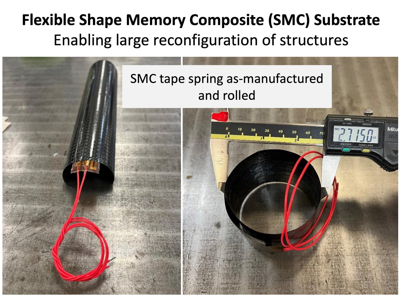
The new SMC substrate has four components: a shape memory polymer separately developed at NASA Langley; a stack of thin-ply carbon fiber sheets; a custom heater and heat spreader between the SMC layers; and integrated sensors (temperature and strain). The shape memory polymer allows the as-fabricated substrate to be programmed into a temporary shape through applied force and internal heating. In the programmed shape, the deformed structure is in a frozen state remaining dormant without external constraints. Upon heating once more, the substrate will return slowly (several to tens of seconds) to the original shape (shown below).
The thin carbon fiber laminate and in situ heating solve three major pitfalls of shape memory polymers: low actuation forces, low stiffness and strength limiting use as structural components, and relatively poor heat transfer. The key benefit of the technology is enabling efficient actuation and control of the structure while being a structural component in the load path. Once the SMC substrate is heated and releases its frozen strain energy to return to its original shape, it cools down and rigidizes into a standard polymer composite part. Entire structures can be fabricated from the SMC or it can be a component in the system used for moving between stowed and deployed states (example on the right). These capabilities enable many uses for the technology in-space and terrestrially.
Aerospace

Aerospace Vehicle Entry Flightpath Control
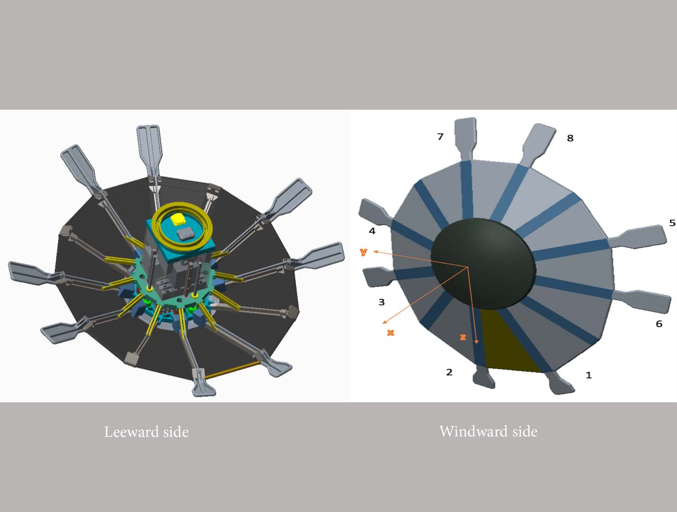
This novel flightpath control system exploits the dihedral effect to control the bank angle of the vehicle by modulating sideslip (Figure 1). Exploiting the dihedral effect, in combination with significant aerodynamic forces, enables faster bank accelerations than could be practically achieved through typical control strategies, enhancing vehicle maneuverability. This approach enables vehicle designs with fewer control actuators since roll-specific actuators are not required to regulate bank angle. The proposed control method has been studied with three actuator systems (figure below), Flaps Control System (FCS); Mass Movement Control System (MMCS); and Reaction Control System (RCS).
• FCS consists of a flap configuration with longitudinal flaps for independent pitch control, and lateral flaps generating yaw moments. The flaps are mounted to the shoulder of the vehicle’s deployable rib structure. Additionally, the flaps are commanded and controlled to rotate into or out of the flow. This creates changes in the vehicle’s aerodynamics to maneuver the vehicle without the use of thrusters.
• MMCS consists of moveable masses that are mounted to several ribs of the DEV heatshield, steering the vehicle by shifting the vehicle’s Center of Mass (CoM). Shifting the vehicle’s CoM adjusts the moment arms of the forces on the vehicle and changes the pitch and yaw moments to control the vehicle’s flightpath.
• RCS thrusters are mounted to four ribs of the open-back DEV heatshield structure to provide efficient bank angle control of the vehicle by changing the vehicle’s roll. Combining rib-mounted RCS thrusters with a Deployable Entry Vehicle (DEV) is expected to provide greater downmass capability than a rigid capsule sized for the same launch


