Search
Propulsion

Improving Hybrid Electric Propulsion Efficiency
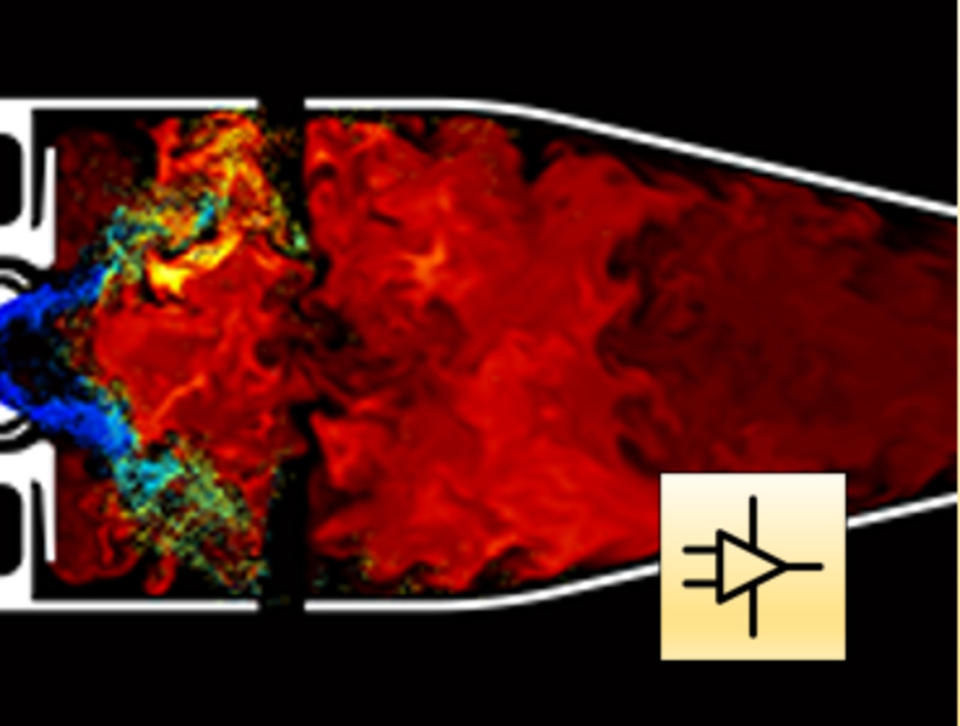
Electrically driven turbine engine compressor and propulsion fans require a large stability margin against stall conditions to avoid unwanted performance issues while undergoing transients in operating conditions. This stability margin, while it maintains safe operation, also necessarily reduces the engine performance. Despite extensive research efforts, no viable alternative methods for reducing the operable stability margin and improving engine performance exist. This current innovation, originally conceived for stall prevention, offers a solution by utilizing a supercapacitor in line with an electric motor and motor controller to rapidly change a compressor or propulsor fan speed. The use of the supercapacitor enables rapid extraction, or addition of power, to prevent the fan from stalling.
Additionally, this novel drive motor may be used for sensing stall event precursor signals by using the motor controller to detect variations in torque on the shaft caused by variance in loading on the blade system. The improved stall avoidance capabilities allow an engine fan to operate more efficiently, providing more thrust for a given frontal area, increasing operational range, reduced weight, and improved operational safety.
The related patent is now available to license. Please note that NASA does not manufacture products itself for commercial sale.
electrical and electronics
Robust High Temperature SiC Op Amps Practical Fabrication
The technology is part of a new generation of NASA Glenn SiC integrated circuits with unprecedented durability in the field of high-temperature electronics. For robust operational amplifiers based on SiC Junction Field Effect Transistors (JFETs), this novel compensation method mitigates issues with threshold voltage variations that are an effect of die location on the wafer. Modern high-temperature op amps on the market fall short due to temperature limits (only 225C for silicon-based devices). Previously, researchers noted that multiple op amps on a single SiC wafer had different amplification properties due to different threshold voltages that varied spatially as much as 18% depending on the circuit's distance from the SiC wafer center. While 18% is okay for some applications, other important system applications demand better precision. By applying this technology to the amplifier circuit design process, the op amp will provide the same signal gain no matter its position on the wafer. The compensation approach enables practical signal conditioning that works from 25C up to 500C.
Power Generation and Storage

CryoQuad
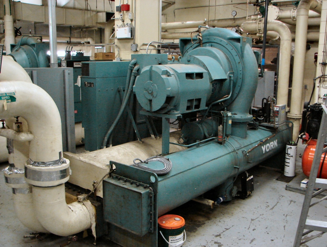
Traditional cryogenic cooling methods, such as pulse-tube and reverse Brayton cryocoolers, are constrained by moving parts, high mass, and limited cooling capacity. Their mechanical complexity increases maintenance needs and reduces reliability, while their bulk adds significant weight penalties to mobile platforms. Although these systems can achieve kilowatt-scale cooling, they struggle to maintain stable, efficient performance under the continuous, high thermal loads required for megawatt-scale superconducting propulsion. The CryoQuad was developed specifically to address these shortcomings, delivering a lighter, more reliable, and higher-capacity solution tailored for superconducting electric propulsion systems.
The novel design utilizes four thermoacoustic Stirling heat engines arranged a quarter wavelength apart in a quad loop configuration. This configuration – wherein each engine has high-power acoustic energy pulled off via power pulse-tube coolers – allows for rapid acoustic wave amplification without moving parts (e.g., pistons, turbines, pumps) or electricity. Importantly, the innovative design eliminates the need for large linear piston generators and large recuperator heat exchangers – two features common in megawatt-scale cryocooling pressure systems today – significantly reducing the overall system mass and complexity. While designed for use with liquid Helium, CryoQuad can utilize a variety of fluids depending on the required cryogenic temperatures.
CryoQuad has the potential to be used in superconducting electric aircraft, other advanced propulsion systems, in-space cryogenic fluid management, cryosurgical cancer treatment probes, MRI systems, cryogenic cooling and packaging systems for superconducting electronics, space fuel depots, and other power applications. CryoQuad is available for patent licensing.
sensors
Streamlined Liquid Level Sensing Using Fiber Optics
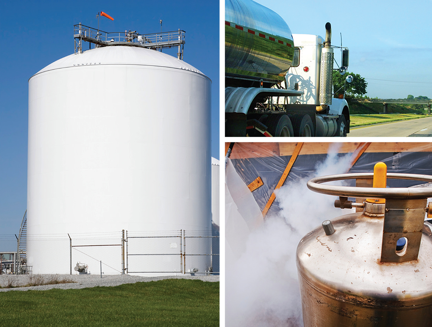
Armstrong has developed a robust fiber optic–based sensing technology that offers extraordinary accuracy in liquid level measurements. The sensing system uses fiber optic Bragg sensors located along a single fiber optic cable. These sensors actively discern between the liquid and gas states along a continuous fiber and can accurately pinpoint the liquid level.
<strong><i>How It Works</strong></i>
The technology uses a resistive heater wire bundled with the optical fiber. The heater is pulsed to induce a local temperature change along the fiber, and the fiber Bragg grating data is used to monitor the subsequent cooling of the fiber. The length of fiber in the liquid cools more rapidly than the portion of the fiber in the gas above the liquid. The measurement system accurately establishes the location of this transition to within 1/4-inch.
<strong><i>Why It Is Better</strong></i>
Armstrong's liquid level sensing technology was originally developed to measure cryogenic liquid levels in rockets, and it represents a significant advancement in the state of the art in this application. Conventional methods for measuring cryogenic liquid levels rely on cryogenic diodes strategically placed along a rod or rack. The diodes are mounted in pre-selected, relatively widely spaced positions along the length of a rod; this configuration provides limited, imprecise data. Furthermore, each diode on the rod has two wires associated with it, which means a single system may require a large number of wires, making installation, connectivity, and instrumentation cumbersome.
Armstrong's novel technology provides liquid measurements with much greater precision, achieving measurements at 1/4-inch intervals. Furthermore, the streamlined system uses just two wires, which greatly simplifies installation and instrumentation. Due to its extraordinary accuracy and ease of use, Armstrong's measurement system offers important advantages for a wide range of applications beyond cryogenic liquids.
<strong><i>In Addition</strong></i>
Researchers have developed a new manufacturing process that improves the ability of fiber optic sensing systems to measure temperature and liquid levels when operating in humid environments. The process involves eliminating moisture from the optical fiber coating, then completing the sensor assembly within humidity-controlled conditions. The resulting sensor hardware provides precise and accurate measurements even when operating in a humid environment.
<b><i>For more information about the full portfolio of FOSS technologies, see DRC-TOPS-37 or visit <a href=https://technology-afrc.ndc.nasa.gov/featurestory/fiber-optic-sensing>https://technology-afrc.ndc.nasa.gov/featurestory/fiber-optic-sensing</a></b></i>
Mechanical and Fluid Systems
Variable-Aperture Reciprocating Reed (VARR) Valve
The VARR valve has been designed to provide a variable-size aperture that proportionately changes in relation to gas flow demand. When the pressure delta between two chambers is low, the effective aperture cross-sectional area is small, while at high delta pressure the effective aperture cross-sectional area is large. This variable aperture prevents overly restricted gas flow. As shown in the drawing below, gas flow through the VARR valve is not one way. Gas flow can traverse through the device in a back-and-forth reversing flow manner or be used in a single flow direction manner. The contour shapes and spacing can be set to create a linear delta pressure vs. flow rate or other pressure functions not enabled by current standard orifices. Also, the device can be tuned to operate as a flow meter over an extremely large flow range as compared to fixed-orifice meters. As a meter, the device is capable of matching or exceeding the turbine meter ratio of 150:1 without possessing the many mechanical failure modes associated with turbine bearings, blades, and friction, etc.
Propulsion

Efficient Megawatt-Scale Cable for Electric Aircraft Propulsion
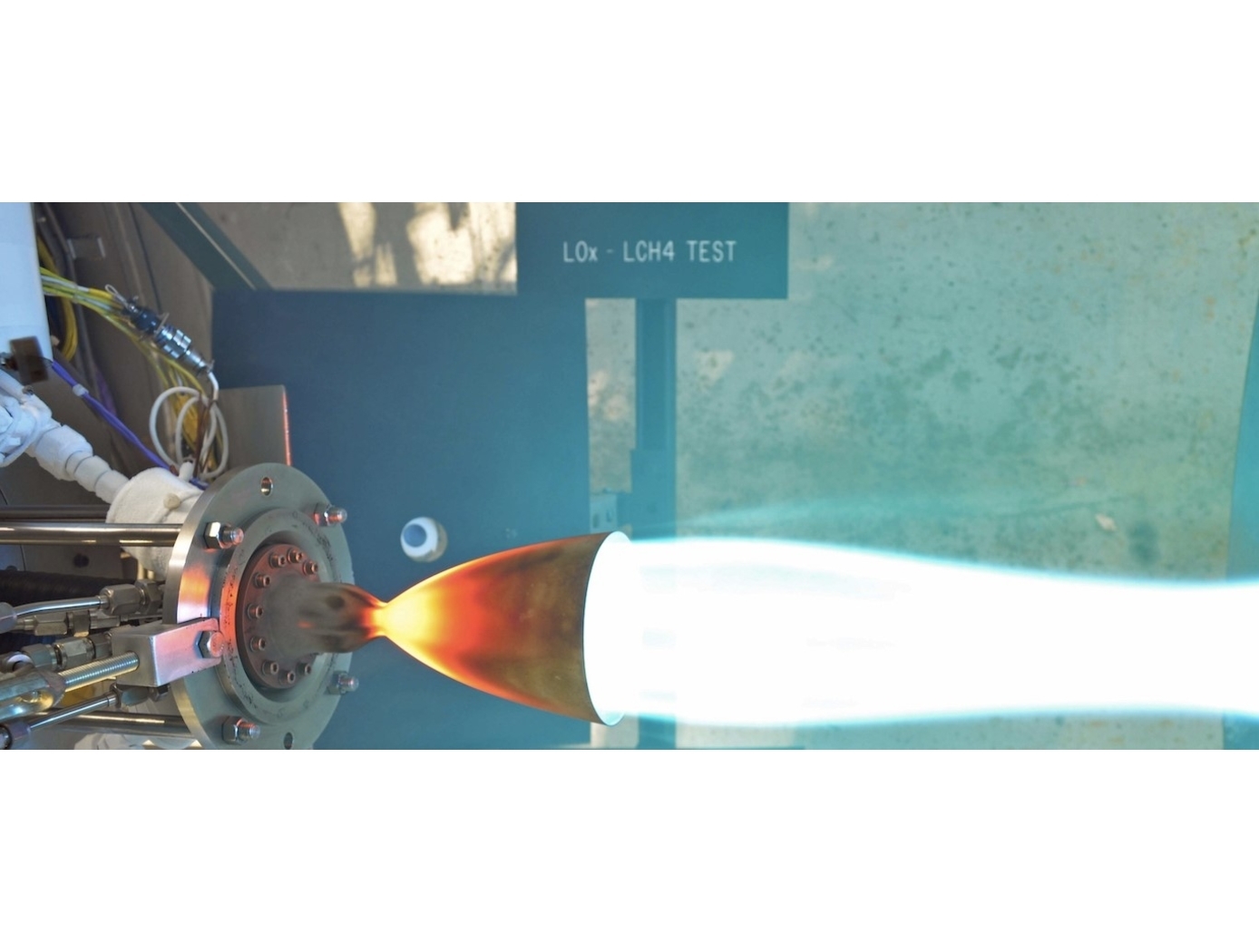
Distilled to its core components, the cable is composed of either a flexible or rigid transmission line with integrated oil-based cooling. Instead of solid wire, current flows through small conductive tubes made of aluminum or copper, which are actively cooled by pump-driven oil flowing through them. Although these smaller conductors have higher resistance and generate more heat, the active cooling offsets this heat generation. This integrated design results in a cable with up to a tenfold improvement in weight per megawatt of power delivered compared to existing solutions.
The use of smaller conductive cables with active cooling reduces the temperature requirements for insulation because more current can be run through the cable. As such, voltage can be reduced, mitigating partial discharge issues, and making insulation an easier engineering challenge. Due to significant weight reductions, specialized duct work is no longer needed. A collection of junction, splicing, and termination components allow the cable to be built into a power and thermal bus to service multiple electrical components.
Initial tests demonstrated the ability to conduct 1,000 amps through actively cooled cables at lower mass than state-of-the-art alternatives, confirming feasibility for next-generation aircraft electrification. However, the cable has broad applications across all vehicle electrification where weight and thermal management are high priorities and is now available for patent licensing.
Sensors

Thin Film Sensor for Ultra High-Temp Measurement
The thin film sensor’s principal advantage lies in its potential to take high frequency temperature measurements from the surface of a reentering spacecraft while simultaneously withstanding the high temperature and oxidizing environment encountered. This data provides engineers with operational phase measurements used to refine the spacecraft’s operational envelope and track flight hardware behavior in addition to providing high frequency temperature measurements that can inform the physics of a boundary layer.
Mismatches in coefficients of thermal expansion (CTE) are expected in TPS-based sensor applications because the metallic materials used for temperature sensing have thermal expansion rates that differ from the rates of the substrate and coating materials in the TPS. At high temperatures during reentry, this mismatch in CTE can create a significant strain differential between the metallic sensor, sensor leads, and the materials to which the sensor and leads are bonded.
High frequency response temperature measurements on the surface of entry spacecraft are not currently possible above ~700 F with existing measurement capabilities. This shortcoming is primarily due to the need for robust sensor behavior at temperatures of several thousand degrees F. The sensor design of this technology preserves the integrity of sensor components while enhancing its high temperature functionality.
The thin film temperature sensor has a technology readiness level (TRL) 5 (Component and/or breadboard validation in relevant environment) and is now available for patent licensing. Please note that NASA does not manufacture products itself for commercial sale.
Materials and Coatings
Oxide Dispersion Strengthened Medium Entropy Alloy
NASA's ODS-MEA maintains properties up to 1100°C and is not susceptible to deleterious phase changes when exposed to extreme temperatures, an issue ubiquitous to Ni- based superalloys such as Inconel-625 and Inconel-718. Yttria particles are dispersed throughout the alloy to maximize strength and creep resistance at high temperatures using a novel fabrication technique. This technique employs an acoustic mixer to stir nano-scale Yttria oxide powder within a metallic matrix powder, creating a film of Yttria surrounding the larger metallic powder particles. Solid components are then produced from this mixture via SLM, during which the laser disperses the Yttria particles throughout the microstructure. Ultimately, the process eliminates the many expensive and time-consuming steps in the production of ODS alloys via traditional mechanical alloying. NASA's process has been shown to fabricate components with 10x improvement in creep rupture life at 1100°C and provides a 30% increase in strength over what is currently possible with 3D printed parts. The new ODS-MEA composition may find applications where ODS alloys are currently used (e.g., those involving extreme thermal environments). Applications may also include areas where such properties are desirable but the resource-intensive nature and/or inability to produce highly complex geometries via conventional processes ultimately renders their use uneconomical or infeasible. Such uses include gas turbine components (for which increasing inlet temperature enables improved efficiency) for power generation, propulsion (rockets, jet engines, etc.), industrial processes, nuclear energy applications, and sample preparation equipment in the mining and cement production industries, among many others.

