Search
aerospace

Adaptive Radar Thresholding for Cluttered Environments
Conventional radar systems often struggle near wind farms, where large moving structures generate erratic echoes that resemble airborne targets. This system addresses that challenge with a smart thresholding mechanism. For each radar “resolution cell” (a segment of monitored space), the system scans Doppler bins and identifies the maximum signal amplitude from non-zero frequency bins. These values are stored in a dedicated memory array and analyzed across multiple radar scans (“dwells”) to generate an adaptive, aggregate threshold. A transition-state delay and configurable tracking sample period stabilize system sensitivity, preventing sudden Doppler anomalies (such as turbine blade movement) from triggering false positives. The system then compares its adaptive threshold against existing fixed thresholds, applying whichever is greater. If a cell corresponds to a known structure, such as a wind turbine (based on a stored radar map), the adaptive threshold is used; otherwise, standard methods apply. The result is a highly flexible system that reduces clutter without sacrificing sensitivity and can be integrated with existing pulse-Doppler radar platforms, including MTI and MTD variants.
Mechanical and Fluid Systems
Ocean Platform Motion Control
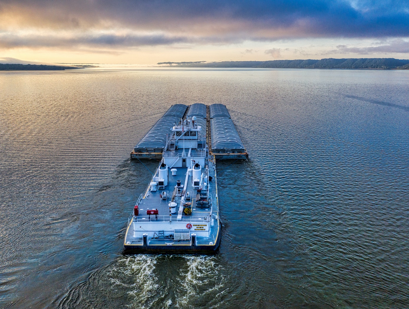
The NASA innovation leverages existing ballast fluid of a maritime structure to proactively mitigate undesirable resonant response characteristics of the platform or vessel. Essentially, this innovation couples water ballast as a functional working mass to the dynamic motion of a floating structure in order to provide passive motion management of the primary structure.
The system can be implemented pre-design or post manufacture. The systems are simple and are easily manufactured, transported, and implemented onto a primary structure.
The NASA technology has been designed (patents applied for) for a range of platform designs and can be further customized depending on the final application requirements. Prototypes have been built and tested in a wind-wave tank test bed at the University of Maine.
Mechanical and Fluid Systems
Tension Element Damping (TED) – With Hydraulics for Large Displacements
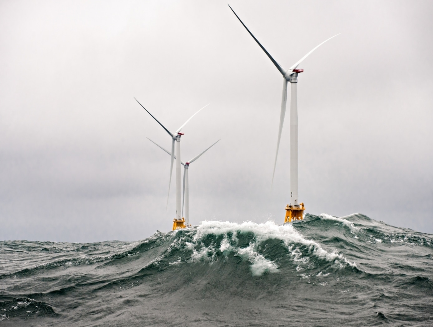
The Rotational Tension Element Damper (RTED) uses a controlled tension line, backed by hydraulics, to damp large displacements in large structures. NASA built RTED prototypes that have been successfully tested on a 170-foot long wind turbine blade in test beds at the University of Maine. In this case, the RTED device damps the vibration of the large, tall turbine blades relative to a stationary anchor structure on the ground using a line and spring coupled to both the blade and the anchor, and controlled by a spool fitted with a one-way clutch. When force is applied, from heavy wind for example, the resulting movement of the tall structure triggers the necessary tension and compression cycles in the system to engage the rotating damper. The reaction force interferes with the rotation speed of the spool and disrupts and damps the vibration in the tall structure. The figure below shows test data for the RTED used on the wind turbine.
Instrumentation

WindiWing: Atmospheric Data Collection Line Climber
This innovative kite system is called the WindiWing, and utilizes aerodynamic forces and moments to control its configuration for both ascent and descent, eliminating the need for an external power source or human intervention. By harnessing wind power, the system autonomously climbs and descends along a pilot kite line, provided sufficient wind conditions exist.
Windiwing includes a set of stops at predetermined upper and lower bounds of the kite line, which define the highest and lowest points the WindiWing can travel. When a stop is hit, the WindiWing changes direction. Therefore, it can sustain extended flight times at different altitudes. Unlike prior solutions, WindiWing is a passive line-climber operating entirely through aero-mechanical principles and does not require electrical power or active control systems for changes in lift. Instead, WindiWing continuously moves between the designated stops along the kite tether, maintaining stable and predictable movement without the need for remote operation or onboard power.
WindiWing is designed with flexibility in mind, offering the ability to carry a range of instrumentation, making it suitable for integration with kite-based systems, tethered balloons, or uncrewed aircraft platforms. The absence of electrical components reduces complexity, enhances reliability, and allows for extended atmospheric data collection with minimal oversight.
By offering a scalable, cost-effective, and power-independent solution, this technology enables long-duration atmospheric profiling at various altitudes, making it an ideal tool for researchers in the fields of atmospheric research, environmental research, and education.
Robotics Automation and Control

Adaptive wind estimation for small unmanned aerial systems using motion data
The technology presents an on-board estimation, navigation and control architecture for multi-rotor drones flying in an urban environment. It consists of adaptive algorithms to estimate the vehicle's aerodynamic drag coefficients with respect to still air and urban wind components along the flight trajectory, with guaranteed fast and reliable convergence to the true values. Navigation algorithms generate feasible trajectories between given way-points that take into account the estimated wind. Control algorithms track the generated trajectories as long as the vehicle retains a sufficient number of functioning rotors that are capable of compensating for the estimated wind. The technology provides a method of measuring wind profiles on a drone using existing motion sensors, like the inertial measurement unit (IMU), rate gyroscope, etc., that are observably necessary for any drone to operate. The algorithms are used to estimate wind around the drone. They can be used for stability or trajectory calculations, and are adaptable for use with any UAV regardless of the knowledge of weight and inertia. They further provide real-time calculations without additional sensors. The estimation method is implemented using onboard computing power. It rapidly converges to true values, is computationally inexpensive, and does not require any specific hardware or specific vehicle maneuvers for the convergence. All components of this on-board system are computationally effective and are intended for a real time implementation. The method's software is developed in a Matlab/Simulink environment, and has executable versions, which are suitable for majority of existing onboard controllers. The algorithms were tested in simulations.
Optics
Reflection-Reducing Imaging System for Machine Vision Applications
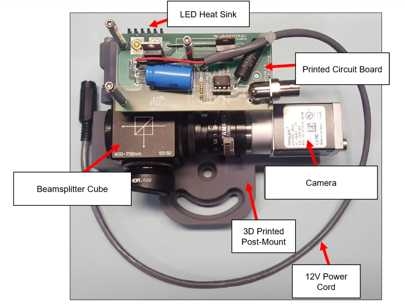
NASA’s imaging system is comprised of a small CMOS camera fitted with a C-mount lens affixed to a 3D-printed mount. Light from the high-intensity LED is passed through a lens that both diffuses and collimates the LED output, and this light is coupled onto the cameras optical axis using a 50:50 beam-splitting prism.
Use of the collimating/diffusing lens to condition the LED output provides for an illumination source that is of similar diameter to the camera’s imaging lens. This is the feature that reduces or eliminates shadows that would otherwise be projected onto the subject plane as a result of refractive index variations in the imaged volume. By coupling the light from the LED unit onto the camera’s optical axis, reflections from windows – which are often present in wind tunnel facilities to allow for direct views of a test section – can be minimized or eliminated when the camera is placed at a small angle of incidence relative to the window’s surface. This effect is demonstrated in the image on the bottom left of the page.
Eight imaging systems were fabricated and used for capturing background oriented schlieren (BOS) measurements of flow from a heat gun in the 11-by-11-foot test section of the NASA Ames Unitary Plan Wind Tunnel (see test setup on right). Two additional camera systems (not pictured) captured photogrammetry measurements.
instrumentation
Assembly for Simplified Hi-Res Flow Visualization
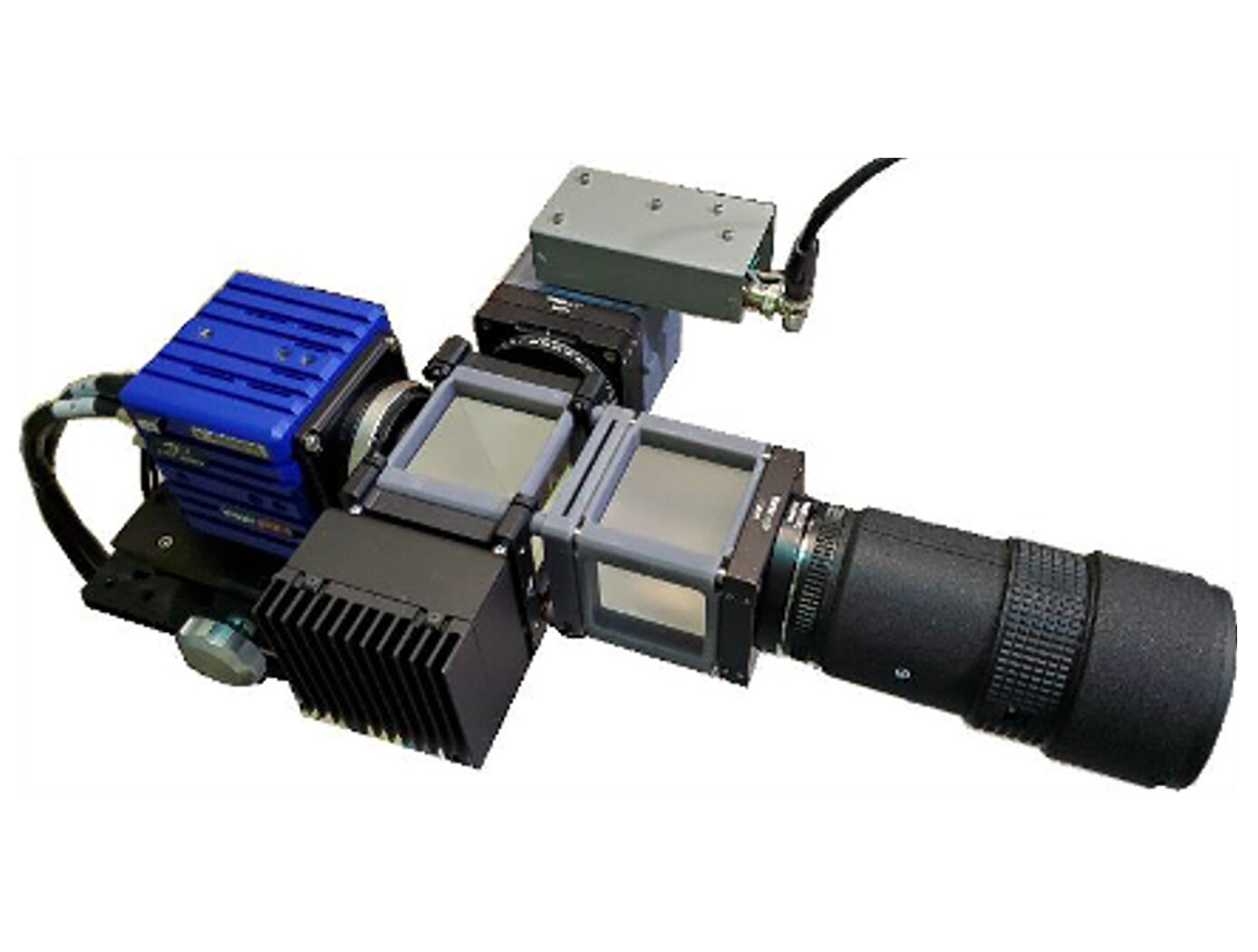
NASAs single grid, self-aligned focusing schlieren optical assembly is attached to a commercial-off-the-shelf camera. It directs light from the light source through a condenser lens and linear polarizer towards a polarizing beam-splitter where the linear, vertically-polarized component of light is reflected onto the optical axis of the instrument. The light passes through a Ronchi ruling grid, a polarizing prism, and a quarter-wave plate prior to projection from the assembly as right-circularly polarized light. The grid-patterned light (having passed through the Ronchi grid) is directed past the density object onto a retroreflective background that serves as the source grid. Upon reflection off the retroreflective background, the polarization state of light is mirrored. It passes the density object a second time and is then reimaged by the system. Upon encountering the polarizing prism the second time, the light is refracted resulting in a slight offset. This refracted light passes through the Ronchi ruling grid, now serving as the cutoff grid, for a second time before being imaged by the camera.
Both small- and large-scale experimental set ups have been evaluated and shown to be capable of fields-of-view of 10 and 300 millimeters respectively. Observed depths of field were found to be comparable to existing systems. Light sources, polarizing prisms, retroreflective materials and lenses can be customized to suit a particular experiment. For example, with a high speed camera and laser light source, the system has collected flow images at a rate of 1MHz.
Mechanical and Fluid Systems

Modified Tuned Liquid Column Damper
When waves move a floating wind turbine, they drive fluid motion inside the MTLCD. This forces air in the vertical tanks through an orifice, increasing pressure much like a spring. As the air discharges, the fluid’s motion is damped and energy is dissipated. The MTLCD also incorporates added damping elements, such as an orifice or variable-aperture reciprocating reed valve, that create resistance to air flow, further controlling fluid motion and dissipating energy.
By integrating these modifications, the MTLCD is easily tuned to the platform’s motions, reducing dependency on platform geometry. Eliminating damping elements from the fluid removes the need for marine-grade hardware, reducing system costs. The MTLCD can also be integrated into existing ballast tanks, maximizing space efficiency with minimal added parts.
While initially developed for NASA’s Floating Wind Turbine Development project, this invention can support vibration mitigation applications across multiple industries, such as infrastructure, maritime systems, and aerospace. By enabling precise tuning of dynamic response characteristics, the MTLCD offers a compact solution for platforms requiring vibration suppression. The technology has completed preliminary design and simulation, is at a TRL 3 (proof-of-concept), and is available for patent licensing.
Mechanical and Fluid Systems

Improved Lunar Regolith Simulant Ion Implantation
Researchers and other technology developers require regolith simulants that accurately emulate the properties of lunar, Martian, and asteroid soils to ensure that the processes, devices, tools, and sensors being developed will be usable in an active mission environment. To move toward higher fidelity regolith simulants, NASA has developed a system that takes typical regolith simulants and implants ions of relevant elements to better simulate the conditions of extraterrestrial soils.
The ion implantation device developed here is composed of three key elements as shown in the figure below: two hopper and rotary valve elements and the acceleration grid structure. To perform the ion implantation, the system is first placed within a vacuum chamber, pumped down, and gases of the elements of interest are pumped into the chamber. The system then first passes a mass of granulated lunar regolith simulant through two stages of hoppers and rotary valves to condition the material. Key to the system is a process for interstitial gas removal (a source of contamination) as shown in the figure on the right. After conditioning, the regolith simulant is passed between two parallel electrodes under a high voltage, accelerating ions of the process gas and implanting those ions within the regolith simulant at controllable depths.
The related patent is now available to license. Please note that NASA does not manufacturer products itself for commercial sale.
Optics

Filtered Ronchi Rulings for Enhanced Schlieren Imaging
The first optic is a 1D Ronchi ruling, where shortpass or longpass filters replace the traditional opaque lines in the grid pattern. The second optic is a 2D Ronchi ruling, where one set of lines is made from shortpass filters and the orthogonal set from longpass filters. By using two colors of light and a color camera in the focusing schlieren system (or a dichroic mirror with two monochrome cameras), the 1D optic enables simultaneous focusing schlieren and other co-linear techniques, while the 2D optic allows for the unambiguous measurement of two orthogonal density gradients in focusing schlieren images.
Unlike standard optical filters, which typically cover an entire substrate, these Ronchi rulings feature alternating clear and filtered regions in structured 1D or 2D patterns. By leveraging color filtering and a color camera, the 1D ruling enables simultaneous focusing schlieren and complementary optical diagnostics, such as Particle Image Velocimetry (PIV), Pressure-Sensitive Paint (PSP), and Thermal-Sensitive Paint (TSP). The 2D ruling enables simultaneous and unambiguous measurement of two orthogonal density gradients, a capability not possible with conventional Ronchi rulings. This advancement significantly improves the accuracy and efficiency of schlieren-based flow measurements. The types of filters are not just limited to shortpass and longpass coatings, but could include notch, bandpass, and multiple-bandpass filter coatings as well.
This design expands the utility of schlieren imaging in high-speed aerodynamics, combustion diagnostics, and other fluid dynamics applications. This Ronchi ruling methodology is at TRL 4 (component and/or breadboard validation in a lab environment) and is available for patent licensing.

