Search
manufacturing

Plasma Deposition of Metal in Composite Panels
NASA's plasma-deposition process provides the ability to tailor various properties while designing functional parts by selecting specific materials and processing parameters to meet the end goal. Specifically, the plasma process deposits metal particles that are heated as they travel axially at low velocity through an inert gas plasma. The accelerated powder particles become molten, strike the substrate fabric (uniaxial, biaxial, and multiaxial) and rapidly solidify, imparting very little heat to the substrate while forming a metal-to-fiber bond, as well as a metal-to-metal bond. The resulting metal-coated fabric is porous, so the polymer matrix can pass through the product precursor during the infusion process. The amount of metal deposited can be
controlled, as can the number of plies of fabric that are ultimately stacked to produce the preform for the polymer matrix infusion process. A variety of infusion processes can be utilized to prepare the FML, including resin transfer molding (RTM), resin film infusion (RFI), and vacuum-assisted resin transfer molding (VARTM). The tailorable aspect of the process allows for specific product design. By varying the combination of metal particle, fiber, fabric type, metal layer thickness, fabric direction, number of layers, polymer matrix resin, infusion process, and cure conditions, the characteristics of the final part can meet the needs of various applications.
Information Technology and Software
Additive Manufacturing Model-based Process Metrics (AM-PM)
Modeling additive manufacturing processes can be difficult due to the scale difference between the active processing point (e.g., a sub-millimeter melt pool) and the part itself. Typically, the tools used to model these processes are either too computationally intensive (due to high physical fidelity or inefficient computations) or are focused solely on either the microscale (e.g., microstructure) or macroscale (e.g., cracks). These pitfalls make the tools unsuitable for fast and efficient evaluations of additive manufacturing build files and parts.
Failures in parts made by laser powder bed fusion (L-PBF) often come when there is a lack of fusion or overheating of the metal powder that causes areas of high porosity. AM-PM uses a point field-based method to model L-PBF process conditions from either the build instructions (pre-build) or in situ measurements (during the build). The AM-PM modeling technique has been tested in several builds including a Ti-6Al-4V test article that was divided into 16 parts, each with different build conditions. With AM-PM, calculations are performed faster than similar methods and the technique can be generalized to other additive manufacturing processes.
The AM-PM method is at technology readiness level (TRL) 6 (system/subsystem model or prototype demonstration in a relevant environment) and is available for patent licensing.
Mechanical and Fluid Systems
Integral Tuned Mass Absorber for Turbine Blades
Additive manufacturing methods (e.g. Laser Metal Sintering) are used to integrally fabricate a tuned-mass vibration absorber inside a turbine blade. The design approach uses an internal column manufactured as part of the blade that is optimized such that the dynamics of the blade damper system are rearranged and reduced according to the well-known science of tuned mass-absorption (TMA). The TMA concept has been implemented successfully in applications ranging from skyscrapers to liquid oxygen tanks for space vehicles. Indeed, this theory has been conceptually applied to bladed-disk vibration, but a practical design has not previously been reported.
The NASA innovation addresses another important challenge for turbine blade vibration damper designs. All existing blade damper solutions are essentially incapable of being reliably predicted, so an expensive post-design test program must be performed to validate the expected response. Even then, the actual magnitude of the response reduction under actual hot fire conditions may never be known. The dynamic response of this tuned-mass-absorber design is both substantial and can be analytically predicted with high confidence, and thus the response can be incorporated fully into the up-front design process.
Manufacturing

Novel Overhang Support Designs for Powder-Based Electron Beam Additive Manufacturing (EBAM)
EBAM technology is capable of making full-density, functional metallic components for numerous engineering applications; the technology is particularly advantageous in the aerospace, automotive, and biomedical industries where high-value, low-volume, custom-design productions are required. A key challenge in EBAM is overcoming deformation of overhangs that are the result of severe thermal gradients generated by the poor thermal conductivity of metallic powders used in the fabrication process. Conventional support structures (Figure 1a) address the deformation challenge; however, they are bonded to the component and need to be removed in post- processing using a mechanical tool. This process is laborious, time consuming, and degrades the surface quality of the product.
The invented support design (Figure 1b) fabricates a support underneath an overhang by building the support up from the build plate and placing a support surface underneath an overhang with a certain gap (no contact with overhang). The technology deposits one or more layers of un-melted metallic powder in an elongate gap between an upper horizontal surface of the support structure and a lower surface of the overhang geometry. The support structure acts as a heat sink to enhance heat transfer and reduce the temperature and thermal gradients. Because the support structure is not connected to the part, the support structure can be removed freely without any post-processing step.
Future work will compare experimental data with simulation results in order to validate process models as well as to study process parameter effects on the thermal characteristics of the EBAM process.
Manufacturing
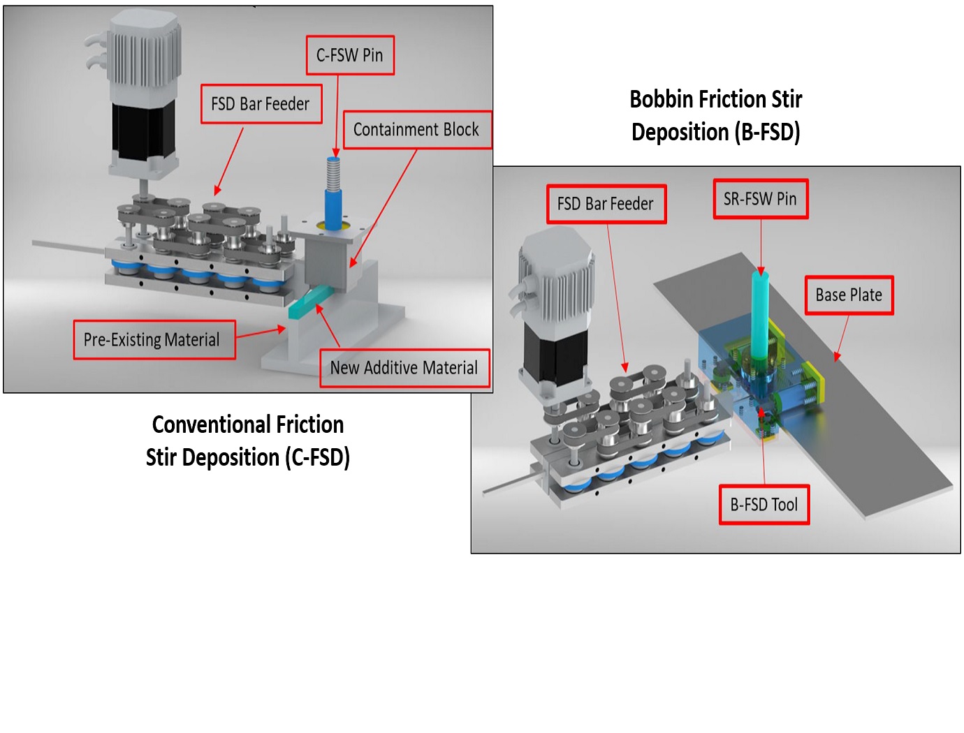
Friction Stir Deposition Innovations
Metal additive manufacturing may be limited by build volumes (i.e., it can be hard to make large parts), post-processing requirements, and upfront costs to buy capital equipment. The two NASA-developed technologies are add-on tools for FSW systems (reducing costs), do not require a printer or print bed, and produce parts with high quality surface finishes.
The C-FSD attachment includes a non-rotating block through which the C-FSW rotating pin is threaded, and a containment plate to hold the plasticized metal within the system. In this technique, raw metal feedstock is fed into one end of the non-rotating block, is heated and plasticized by the C-FSW pin, and is driven out the other side of the block. The C-FSW pin is used to join the new material to the pre-existing layer.
The B-FSD tool uses a dual-shoulder design to print outward from the edge of the base panel. The B-FSD process uses the same feed system as the C-FSD, but utilizes the bobbin/SR-FSW pin's dual shoulders (i.e., containing the metal on both the top and bottom) enabling more complex structures to be made, and the ability to print varying thickness depositions in a single pass.
The Additive C-FSD and B-FSD end effector tools are both at technology readiness level (TRL) 4 (component and/or breadboard validation in laboratory environment) and are available for patent licensing.
Manufacturing

Rapid Aerogel Prototyping Using 3D Printing
To overcome the challenges of conventional molding, researchers at NASA Glenn have developed a rapid prototyping approach for three-dimensional printing of polymer aerogels using deposition into a viscous, sacrificial support medium. The sacrificial support stabilizes the aerogel deposition, allowing precise layer-by-layer construction of self-supporting aerogel networks that would otherwise be unprintable in air. Following printing and gelation of the polymer network, the printed structure is gently removed from the sacrificial medium, yielding a freestanding aerogel precursor with high shape fidelity.
This method decouples printability from intrinsic material viscosity and enables rapid iteration of aerogel geometries, offering a scalable pathway for additive manufacturing of ultra-lightweight, architected polymer aerogels with tailored geometries, while retaining microstructural, mechanical, and thermal properties.
The method involves:
1. Forming a solution comprised of a polymer precursor, cross-linker, solvent, and catalyst to create a dilute polymer solution.
2. 3D printing the polymer precursor directly into the sacrificial support medium.
3. Following printing and network formation, the structure is removed from the sacrificial medium through a low-stress extraction process, yielding a freestanding polymer aerogel precursor that retains the as-printed geometry with high fidelity.
The sacrificial medium functions as a temporary, conformal support matrix that stabilizes each deposited droplet or filament in situ, enabling freeform construction of aerogel. This strategy enables the fabrication of highly porous, interconnected networks with controlled feature resolution across multiple length scales, while maintaining the intrinsic low density and high surface area required for aerogel performance.
manufacturing
.jpg)
Interim, In Situ Additive Manufacturing Inspection
The in situ inspection technology for additive manufacturing combines different types of cameras strategically placed around the part to monitor its properties during construction. The IR cameras collect accurate temperature data to validate thermal math models, while the visual cameras obtain highly detailed data at the exact location of the laser to build accurate, as-built geometric models. Furthermore, certain adopted techniques (e.g., single to grouped pixels comparison to avoid bad/biased pixels) reduce false positive readings.
NASA has developed and tested prototypes in both laser-sintered plastic and metal processes. The technology detected errors due to stray powder sparking and material layer lifts. Furthermore, the technology has the potential to detect anomalies in the property profile that are caused by errors due to stress, power density issues, incomplete melting, voids, incomplete fill, and layer lift-up. Three-dimensional models of the printed parts were reconstructed using only the collected data, which demonstrates the success and potential of the technology to provide a deeper understanding of the laser-metal interactions. By monitoring the print, layer by layer, in real-time, users can pause the process and make corrections to the build as needed, reducing material, energy, and time wasted in nonconforming parts.
manufacturing
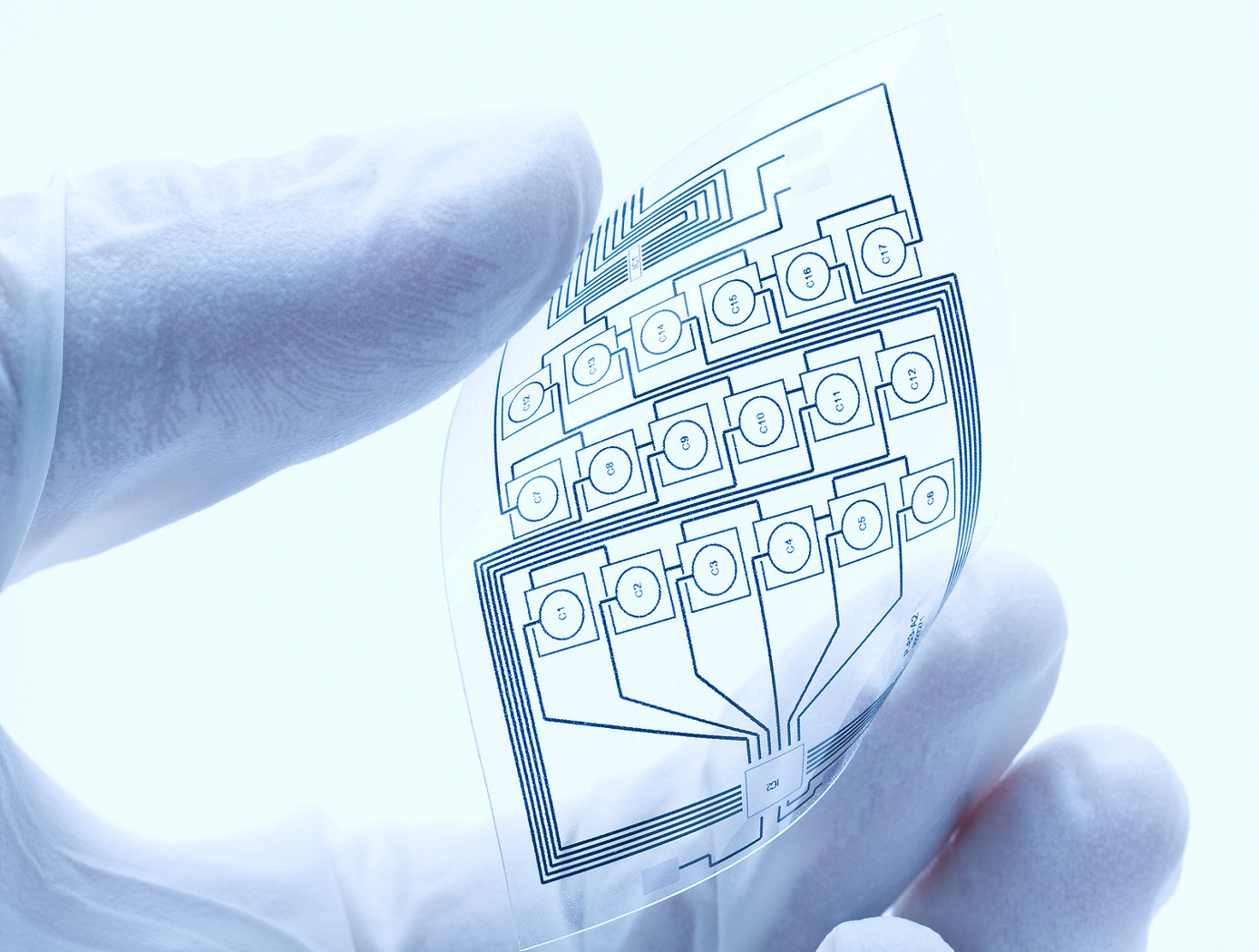
Fabricating printable electronics and biosensor chips
The plasma system consists of a glass tube with a diameter of 0.5 mm or larger, if desired. The electrodes are separated by 10 mm. Helium, argon or cold dry air can be used as a plasma gas source. An applied high voltage between the electrodes causes the gas to breakdown within the central core of the glass capillary generating atmospheric plasma. Nanostructures colloids/organic/inorganic precursors are placed in a glass container with an inlet and outlet for carrier gas and are seated on an ultrasonic nebuliser. The aerosol is then carried into the plasma stream by the carrier gas and is deposited.
The atmospheric plasma deposition system can be modified for depositing multiple materials, either simultaneously or sequentially, and for high-throughput processing by having multiple jets. Each capillary can either be connected to the container containing a single precursor material or to different containers containing different precursor materials to facilitate multiple depositions. The multi-jet plasma system can be automated and controlled individually to precisely control surface characteristics. This technique is independent of the chosen substrate, and has proven to work for many substrates, including paper, plastic, semiconductors and metals.
Manufacturing

Optimization of X-Ray CT Measurement Accuracy for Metal AM Components
This NASA innovation is a method for quantifying and improving accuracy of X-Ray CT-based metal AM part inspection by comparing X-Ray CT data with a high-fidelity 2D surface imaging technique such as surface profilometry. Using surface profilometry that has a NIST-traceable calibration, the technique guarantees a specific level of high fidelity, allowing surface profilometry data to serve as a ground truth reference with which to judge X-Ray CT accuracy and detectability.
To deploy the method, both 3D X-Ray CT data and 2D high-fidelity surface images are acquired on the same metal AM part. 3D X-Ray CT data is then segmented and reoriented to extract a 2D X-Ray CT surface image. Measurements of features (e.g., surface-breaking porosity) are then made in both datasets, followed by a comparison of various metrics. This comparison serves two purposes: (a) quantifying the accuracy of the X-Ray CT inspection performed, and (b) providing an objective function which can be minimized to optimize X-Ray CT inspection. The objective function allows engineers to tune X-Ray CT parameters to minimize the function. These optimized parameters can then be implemented to achieve higher accuracy and defect detection reliability in X-Ray CT imaging. Once an X-Ray CT process is optimized for a specific metal AM component, analysis and certification can be accelerated.
This technology helps develop X-Ray CT-based metal AM part inspection processes with high accuracy and reliable detectability. Industries for which metal AM parts are desirable and safety, reliability, and fatigue life is of concern (e.g., aerospace, commercial space, automotive, medical) could benefit from the invention. Companies including X-Ray CT inspection system manufacturers using optical sensors and software, NDE data analysis software providers, and end-users in the industries may be interested in licensing this NASA invention.
Manufacturing

Cladding and Freeform Deposition for Coolant Channel Closeout
LWDC technology enables an improved channel wall nozzle with an outer liner that is fused to the inner liner to contain the coolant. It is an additive manufacturing technology that builds upon large-scale cladding techniques that have been used for many years in the oil and gas industry and in the repair industry for aerospace components. LWDC leverages wire freeform laser deposition to create features in place and to seal the coolant channels. It enables bimetallic components such as an internal copper liner with a superalloy jacket. LWDC begins when a fabricated liner made from one material, Material #1, is cladded with an interim Material #2 that sets up the base structure for channel slotting. A robotic and wire-based fused additive welding system creates a freeform shell on the outside of the liner. Building up from the base, the rotating weld head spools a bead of wire, closing out the coolant channels as the laser traverses circumferentially around the slotted liner. This creates a joint at the interface of the two materials that is reliable and repeatable. The LWDC wire and laser process is continued for each layer until the slotted liner is fully closed out without the need for any filler internal to the coolant channels. The micrograph on the left shows the quality of the bond at the interface of the channel edge and the closeout layer; on the right is a copper channel closed out with stainless.

