Search
communications
Cascaded Offset Optical Modulator
A unique challenge in the development of a deep space optical SDR transmitter is the optimization of the ER. For a Mars to Earth optical link, an ER of greater than 33 dB may be necessary. A high ER, however, can be difficult to achieve at the low Pulse Position Modulation (PPM) orders and narrow slot widths required for high data rates. The Cascaded Offset Optical Modulator architecture addresses this difficulty by reducing the width of the PPM pulse within the optical modulation subsystem, which relieves the SDR of the high signal quality requirements imposed by the use of an MZM. With the addition of a second MZM and a variable time delay, all of the non-idealities in the electrical signal can be compensated by slightly offsetting the modulation of the laser. The pulse output is only at maximum intensity during the overlap of the two MZMs. The width of the output pulse is effectively reduced by the offset between MZMs. Measurement and analysis of the system displayed, for a 1 nanosecond pulse width, extinction ratios of of 32.5 dB, 39.1 dB, 41.6 dB, 43.3 dB, 45.8 dB, and 48.2 dB for PPM orders of 4, 16, 32, 64, 128, and 256, respectively. This approach is not limited to deep space optical communications, but can be applied to any optical transmission system that requires high fidelity binary pulses without a complex component. The system could be used as a drop-in upgrade to many existing optical transmitters, not only in free space, but also in fiber. The system could also be implemented in different ways. With an increase in ER, the engineer has the choice of using the excess ER for channel capacity, or simplifying other parts of the system. The extra ER could be traded for reduced laser power, elimination of optical amplifiers, or decreased system complexity and efficiency.
Communications

Boosting Quantum Communication Efficiency
The technology consists of an array of quantum photon sources connected via a sophisticated switching network. This system is designed to produce single pairs of entangled photons at a high rate while actively suppressing the generation of multiple pairs. The key innovation lies in its ability to detect and eliminate instances where two or more entangled photon pairs are generated, effectively reducing noise in the quantum system.
The technology operates by providing a heralding pulse that notifies the external system of successful entangled photon generation. When multiple pairs are detected, they are prevented from entering the rest of the system, thereby maintaining the integrity of the quantum information.
By combining multiple single-photon sources through its switching network, the technology not only reduces noise but also increases the overall single photon pair generation rate. This dual approach of noise reduction and increased generation efficiency improves qubit transmission rates, potentially by a factor of 10 to 100 over current methods.
While still in the early stages of development, the source array represents a significant advancement in quantum communication systems. It addresses the critical need for high-fidelity entangled photon sources, which are essential for various quantum applications, including entangling sensor networks, quantum computer networks, and quantum key distribution for secure communications.
As quantum technologies continue to evolve, this source array technology positions itself as a crucial component in the development of large-scale, efficient quantum networks, offering a solution to one of the fundamental challenges in quantum information transmission.
communications
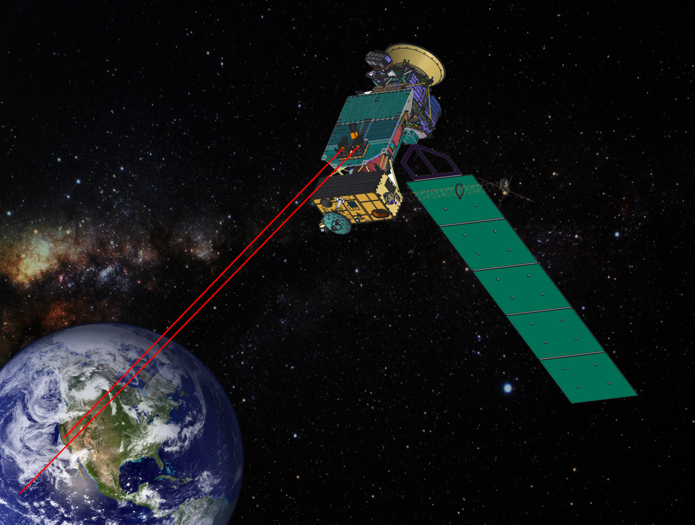
Fine-pointing Optical Communication System Using Laser Arrays
A new method is described for optical data transmissions from satellites using laser arrays for fine pointing of laser beams that use body pointing. It combines a small lens system and a VCSEL/Photodetector Array in a novel way to provide a fine pointing capability for laser beams that are pointed by body pointing of a CubeSat. As Fig. 1 shows, an incoming laser beam (green or blue, with rightward arrows), transmitted from a ground terminal, enters the lens system, which directs it to an element of the pixel array (gray rectangle). Each element, or pixel, consists of a VCSEL component/photodetector pair. The photodetector detects the incoming beam, and the VCSEL component returns a modulated beam to the lens system (green or blue, with leftward arrows), which sends it to the ground terminal. As the incoming beam changes direction, e.g., from the blue to the green incoming direction, this change is detected by the adjacent photodetector, and the laser paired with that photodetector is turned on to keep the outgoing laser beam on target. The laser beams overlap so that the returning beam continues to point at the ground terminal. The VCSEL component may consist of a single VCSEL or a cluster of VCSELs. Figure 2 shows the propagation of two overlapping laser beams. The system can very accurately point finely focused diffraction-limited laser beams. Also, simultaneous optical multiple access (OMA) is possible from different transceivers within the area covered by the laser array. For this electro-optical system, reaction times to pointing changes and vibrations are on the nanosecond time scale, much faster than mechanical fine pointing systems.
Information Technology and Software
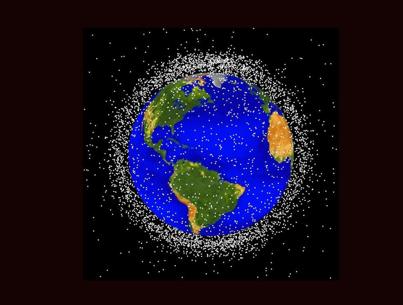
Space Traffic Management (STM) Architecture
As ever larger numbers of spacecraft seek to make use of Earth's limited orbital volume in increasingly dense orbital regimes, greater coordination becomes necessary to ensure these spacecraft are able to operate safely while avoiding physical collisions, radio-frequency interference, and other hazards. While efforts to date have focused on improving Space Situational Awareness (SSA) and enabling operator to operator coordination, there is growing recognition that a broader system for Space Traffic Management (STM) is necessary. The STM architecture forms the framework for an STM ecosystem, which enables the addition of third parties that can identify and fill niches by providing new, useful services. By making the STM functions available as services, the architecture reduces the amount of expertise that must be available internally within a particular organization, thereby reducing the barriers to operating in space and providing participants with the information necessary to behave responsibly. Operational support for collision avoidance, separation, etc., is managed through a decentralized architecture, rather than via a single centralized government-administered system.
The STM system is based on the use of standardized Application Programming Interfaces (API) to allow easier interconnection and conceptual definition of roles to more easily allow suppliers with different capabilities to add value to the ecosystem. The architecture handles basic functions including registration, discovery, authentication of participants, and auditable tracking of data provenance and integrity. The technology is able to integrate data from multiple sources.
Instrumentation

Sensitive, Compact 1x8 Array 530-600 GHz Receiver
This NASA invention is a highly compact and sensitive 530-600 GHz, 1x8 receiver array employing a multi-pixel approach to enhance simultaneous detection capabilities. The receiver has a conversion loss of <11dB, noise temperature of less than 2000 K at 540 GHz, and a wide IF bandwidth of ~70 GHz. The system reduces size, weight, and power consumption (SWaP) by 3-4x and increases sensitivity by factor of 2x or more relative to current state-of-the-art cascaded systems.
The invention includes a power splitter circuit with an attenuation card, a mixer circuit coupled to an output of the power splitter circuit, and an antenna assembly coupled to an output of the mixer circuit. The splitter is a four-port waveguide designed with high position tolerance, and the waveguide attenuator provides a better than 20dB attenuator and balances the power split. A compact and high-efficiency Tripler circuit is integrated into the array system, that multiplies input frequency by a factor of 3. The system includes a sensitive, broadband sub-harmonic mixer circuit for 530-600 GHz frequency band operation (enabling the simultaneous detection of more than fourteen molecular species in this range e.g., water, deuterium oxide, oxygen, etc.) and integrated diagonal horn antennas to provide 24 dB gain with 9mm antenna spacing. Note that while originally designed for the 530-600 GHz band for remote sensing purposes, the design topology of the receiver can be easily scaled to support frequencies ranging from 1 GHz to > 1 THz and the center frequency can be tuned by adjusting design parameters.
While NASA originally developed this receiver to enable miniaturized, low power consumption, high sensitivity heterodyne-based submillimeter wave spectrometers for small satellite-based planetary atmospheric sensing, potential applications of the novel receiver are broad. The multi-pixel, wideband receiver can be used in spectrometer and radar systems for applications including astronomy, plasma fusion, military, and emerging communication technologies such as 5G and 6G. The invention is available for patent licensing.
communications
Vortex Radiometer for Wireless Communications
The Vortex Radiometer (VR) creates concentric, annular antenna beam patterns that measure sky-noise temperature. Annular antenna patterns are created by imparting orbital angular momentum into the electric field received by the antenna using spiral phase plates placed in front of the antenna aperture, generating multiple radiometer channels. Data points are then collected by plotting the measured noise temperature of each radiometer channel as a function of time. Noise temperature increases as a noise source (e.g., weather-related noise, signal interference, etc.) traverses the antenna beam patterns. An algorithm is then used to correlate noise temperature peaks in adjacent beams and to determine when a fade will occur, how long the fade will last, and how intense the fade will be. With this information, effective and efficient strategies can be implemented using cognitive communication and antenna systems to autonomously select the optimum fade-mitigation technique and parameter (e.g., increasing the transmission power, adjusting the modulation and/or coding scheme, etc.).
NASA's VR system has been prototyped, including the radiometer device and the algorithm for characterizing noise sources based on VR data. Simulations have shown that a VR system can instruct an existing cognitive antenna to switch between Ka- and X-Band communications in order to avert interference from small diameter noise sources.
Any high-performance communication systems operating in RF or optical frequencies may benefit from NASA's VR capabilities.
Communications
Optical Transceiver Method of QKD Encryption Suite of Technologies
The core of the technology is the SAW division de-multiplexing method (LEW-19920-1). It uses a commercially available double-clad fiber optic cable with a 9um core and a 105um first cladding. By optimizing the wavelengths of the QKD photon and data transmission, a single focusing lens can create a diffraction pattern that directs the QKD photons to the 9um core and the data signal to the 105um secondary core.
Key components of the system include:
• SOA Driver With Wideband Current Control (LEW-19913-1): This device allows a semiconductor optical amplifier (SOA) or laser to be driven with an arbitrary current at a rate of over 100 MHz. This enables the rapid generation of sub-nanosecond laser pulses with one of four polarization states, which is necessary for QKD.
• Random Bit Generator with Linear Feedback Shift Register LFSR Scrambler (LEW-20058-1): This device produces random bits by combining the output of a noise source with a pseudorandom bitstream from the LFSR. This allows a random basis set to be generated on demand for a polarization modulator.
• Variable-length quantum key conversion (LEW-20224-1): Since QKD operations produce keys of varying lengths, a strategy was developed to "digest" these raw keys using a hash function, such as SHAKE256. This process generates a fixed-length output that is useful for symmetric encryption schemes like AES256.
• The system also incorporates a Discretization Algorithm for Numerical Wave Optics Simulations (LEW-20119-1), which can accurately model the effects of atmospheric turbulence on the propagating optical beam.
Robotics Automation and Control

Robotic system for assembly and maintenance of lightweight reconfigurable structures
To enable the goal of autonomous assembly of high performing structures, a robot system must be able to travel across a lattice structure in all dimensions, transport and align a unit cell module to the correct location and fasten the module to the existing structure. In this system, a team of multiple mobile bipedal robots work together to carry, transfer, and place 3D-lattice modules (e.g., cuboctahedron voxels) to form a 3D lattice structure. The team of mobile bipedal robots autonomously provide transportation, placement, unpacking, and assembly of voxel modules into functional structures and systems. As the team of mobile bipedal robots live and locomote on the 3D-lattice structure, they monitor health and performance, enabling repair and reconfiguration when needed. The mobile bipedal robots work together in different roles, for example, one as a cargo transport robot and the other as a crane robot. The cargo transport robot and the crane robot work together to move the voxels from one location to another. Each robot includes at least one electronic control module that receives commands from another robot or a central control system. A central control system implements a plan to control the motion sequences of the robots to maximize efficiency and to optimize the work required to completely assemble a structure. The plan is pre-computed or computed during implementation by the central control system or the robots themselves, according to algorithms that utilize the regularity of the lattice structure to simplify path planning, align robotic motions with minimal feedback, and minimize the number of the degrees of freedom required for the robots to locomote across and throughout the 3D-lattice structure and perform structural assembly.

